________________________________________________________________________________
Kubota B6000, B7000, B7001 - Transmission
Kubota B6000, B7000, B7001 Tractor - Clutch
Adjustments
Adjustment of clutch pedal
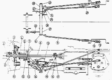
1 - Bearing, 2 - Oil Sea, 3 - Clutch Disc Assy, 4 - Thrust Ball Bearing,
5 - Bearing Holder, 6 - Brake Pedal Shaft, 7 - Clutch Release Fork, 8 -
Propeller Shaft, 9 - Brake Rod, 10 - Step, 11 - Pressure Plate, 12 -
Ring, 13 - Clutch Rod, 14 - Spring, 15 - Flange, 16 - Rubber, 17 - Pin
Flange, 18 - U-Joint, 19 - Differential Lock Lever, 20 - Brake RH Pedal,
21 - Brake LH Pedal, 22 - Rod, 23 - Collar, 24 - Differential Lock
Pedal, 25 - Spring, 26 - Differential Lock Pedal Shaft, 27 - Clutch
Pedal, 28 - Differential Lock Rod
Adjustment of clutch pedal play
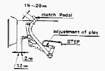
The play of the clutch pedal is governed by the clearance between the
release lever and the ball bearing. The clearance has been set to 0 098
to 0.12 in (2.5 to 3 mm) before the tractor left the factory. However,
me clearance changes as the tractor is used. The general tendency is for
the play to increase at the beginning but will decrease with use. if the
clutch pedal were to be used with no play, it would cause troubles. Be
sure to make checks at time of routine checks and maintenance, and if
necessary, make the necessary adjustment.
Precaution in operating clutch
Clutch should serve to transmit power without loss and furthermore
should engage or disengage accurately whenever so required. For this
reason, operation and maintenance services should be performed very
carefully. The clutch pedal should be depressed speedily to disengage
the clutch arid returned slowly to reengage it. Retrain by all means
from leaving the foot on the pedal while operating the tractor or from
traveling with clutch half engaged. Kubota B6000, B7000, B7001 tractor
should not be jerked with a load more than the specified not be used for
long period with overload, because otherwise the life of the clutch will
be shortened or various troubles may likely be caused, in case of long
storage, keep the clutch disengaged by using a piece of wood to lock the
pedal. Engine starting is only possible when the clutch is disengaged.
Kubota B6000, B7000, B7001 Tractor -
Transmission Assembly
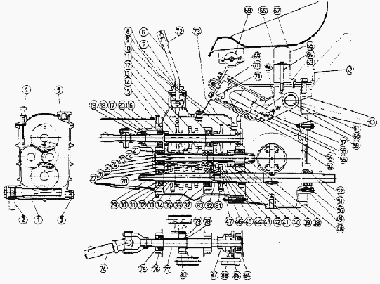
Kubota B6000, B7000, B7001 Transmission Parts: 1 - Oil
Filter, 2 - Pipe, 3 - Plug, 4 - Oil Gauge, 5 - Cap, 6 - Change Lever, 7
- Spring, 8 - Cover, 9 - Ball Bearing, 10 - 13T-28T Gear, 11 - Ball
Bearing, 12 - 20T-25T Gear, 13 - 29T Gear, 14 - 4th Shaft, 15 - Needle
Bearing, 16 - Ball Bearing, 17 - 1st Shaft, 18 - Ball Bearing, 19 - Oil
Seal, 20 - 1st Shaft Cover, 21 - Ball Bearing, 22 - Collar, 23 - Collar,
24 - 2nd Shaft, 25 - 14T Gear, 26 - 18T Gear, 27 - 23T Gear, 28 - 30T
Gear, 29 - 3rd Shaft, 30 - Oil Seal, 31 - Ball Bearing, 32 - Collar, 33
- Thrust Collar, 34 - Bush, 35 - 29T Gear, 36 - 20T-25T Gear, 37 - Ball
Bearing, 38 - Spiral Bevel Gear Pinion, 39 - Ball Bearing, 40 - Ball
Bearing, 41 - 15T Gear, 42 - Collar, 43 - 30T Gear, 44 - Ball Bearing,
45 - Bush, 46 - Collar, 47 - Ball Bearing, 48 - Differential Gear Case,
49 - 5th Shaft Cover, 50 - Ball Bearing, 51 - Oil Seal, 52 - 5th Shaft,
53 - Plate, 54 - O-Ring, 55 - Oil Pressure Piston, 56 - Oil Pressure
Piston Rod, 57 - Arm Pin, 58 - Lock Washer, 59 - Oil Pressure Arm, 60 -
Oil Pressure Arm Shaft, 61 - Case Rear Cover, 62 - Washer, 63 -
Breather, 64 - Collar, 65 - Seat Rear Support, 66 - Seat, 67 - Seat
Cover, 68 - Cushion, 69 - Seat Front Support, 70 - O-Ring, 71 - Cylinder
Cap, 72 - Lever Grip, 73 - Case Front Cover, 74 - Front Axle Drive
Shaft, 75 - Oil Seal, 76 - Ball Bearing, 77 - Reverse Shaft, 78 - 1st
Shaft Collar, 79 - Bush, 80 - 22T Gear, 81 - 28T Gear, 82 - Bush, 83 -
Transmission Case, 84 - Ball Bearing, 85 - 1st Shaft Collar, 86 - 25T
Gear, 87 - Front Wheel Drive Clutch
Kubota B6000, B7000, B7001 - Transmission case
disassembly
Drain out the oil from the right and left bottom of the differential
gear case and bottom of the transmission case. Remove front and rear
case cover. Remove left and right axle case, and draw out differential
gear shaft, differential gear lock fork and axle. Pull out 5th shaft.
Unscrew the bolts connecting transmission case and differential gear
case and divide the cases. Remove 28T gear, shift fork, and shift fork
rod. Pull out spiral bevel gear pinion. Pull out 25T gear on rear end of
back shaft and the ratchet clutch. Remove the auxiliary speed change
shift fork. Remove the 1st shaft cover and pull out the 1st shaft.
Needle bearing and collar are in the 1st shaft so be careful that they
do not drop out. Remove the 4th shaft to the back. Pull out the reverse
shaft. Pull out the 2nd shaft to the front. Pull out the 3rd shaft to
the back. Pull out the rotary speed change shift fork.
Kubota B6000, B7000, B7001 - Transmission case
assembly
Assemble the rotary speed change lever, auxiliary speed change lever and
front axle drive clutch lever. Assemble the 3rd shaft (The front and
back thrust collar for the 29T gear should be assembled so that the side
with notches faces the gear side). Assemble the rotary speed change
shift fork and the shift rod. The shift rod should be assembled with the
O-ring groove in the front side. Push in from the front, being very
careful net to drop the balls. Assemble the 2nd shaft. Assemble the
reverse shaft. The front and back collar for the 25T gear at the rear
part of the reverse shaft should be assembled so that the side with the
notches face the gear side. The 22T gear should be assembled with the
chamber part in the front. Assemble the 4th shaft.
Assemble the 1st shaft and 1st shaft cover. Knock in the 6202 bearing of
the 2nd shaft and 4th shaft. Assemble the auxiliary speed change shift
fork and shift fork shaft. The shift fork shaft is symmetrical so there
is no right or left side to the shaft. Assemble the spiral level gear
pinion. Assemble with the gear and bearing in the assembled condition.
Assemble the 28T gear, shift fork and shift rod. Assemble at the front
and of the shift rod of the 28T gear which is engaged with the 5th
shaft, and engage on the spline of the 3rd shaft. Assemble the
differential in the differential case. In ordinary cases 1 shim each is
inserted on the outer side of the right and left bearing of the
differential assembly. Assemble the differential gear case to the
transmission case. Check the engagement of the differential bevel gear
and the backlash. The backlash should be 0.13-0.25 mm. Assemble the 5th
shaft. Insert from the rear end of the differential gear case, turn and
engage to the spline of the 28T gear Put on the cover.
Assemble the axle and the differential gear. First put in the axle and
then put in the differential gear shafts. At the same time, put on the
differential lock fork and the fork rod on the right side. Assemble the
axle cover and lower link bracket. Operate the differential lock to
check whether it operates correctly. Assemble the front and rear case
covers. At the time of assembling the front case cover, put the main
speed change gear to neutral, and check to make sure that the fork of
the main speed change shift rests in the fork groove of the gear and
works correctly.
Also be sure that the auxiliary speed change lever is
positioned correctly on the auxiliary speed charge fork groove. After
tightening the cover bolts, check to see whether the main speed change
lever and auxiliary speed charge lever works property. When the
hydraulic arm has been disassembled, be sure to align the assembly mark
of the hydraulic arm shaft and the hydraulic arm at the time of
assembly. When assembling the lift arm, be sure to align correctly. Do
not remove check rod and operate the hydraulic arm. The hydraulic arm
will hit the rear part of the differential gear case and might damage
the case.
Kubota B6000, B7000, B7001 - Adjustment of
spiral bevel pinion and gear
Adjustment of the spiral bevel pinion and gear is effected by shims used
on the differential bearing cases. At the time of disassembly, be
attentive to the shims used there and be careful not to lose them. In
assembling, return the unassembled shims to their original places, and
then check meshing and backlash of the gear teeth. If both are correct,
proceed with assembly. However, if a tractor has been put to a long
period of service, it generally requires an adjustment in this unit,
which should be made in the following order. Adjustment in clearance of
differential complete, to differential bearing cases.
Since the differential is supported on the right and left by ball bearings, and improper adjustment in shims used on the bearing cases will result in a differential which is too tight to turn smoothly or which rattles to right and left not allowing the pinion and gear to mesh properly. For correcting such troubles, gradually decrease in the former case and increase in the latter case the number of shims on bearing cases until the differential complete turn lightly. For easier adjustment, it is recommended that me spiral bevel pinion shaft be removed from the assembly during the service. After the above shim adjustment, attend to the following adjustment.
Adjustment in backlash and meshing of spiral
bevel pinion and gear. This adjustment is very important. Whether this
has been performed correctly or not seriously affects the life of the
gears and consequently the durability of the tractor. Therefore, make
the adjustment with close care. Simple ways of judging the results of
adjustment are: Backlash - Fill and impress solder between teeth meshed
and measure the thickness of impressed solder with a micrometer. If the
measurement is 0.1 to 0.2 mm), the adjustment is correct. Contact of
teeth - Apply a very thin coat of rod thinned with oil to contact
surfaces of several teeth of the pinion. Mesh and turn the pinion with
the gear lightly.
________________________________________________________________________________
________________________________________________________________________________________
________________________________________________________________________________________
| KUBOTA TRACTORS SPECIFICATIONS |
________________________________________________________________________________________
________________________________________________________________________________________
________________________________________________________________________________________
________________________________________________________________________________________
________________________________________________________________________________________
________________________________________________________________________________________
________________________________________________________________________________________
________________________________________________________________________________________
________________________________________________________________________________________
________________________________________________________________________________________
________________________________________________________________________________________
________________________________________________________________________________________
________________________________________________________________________________________
________________________________________________________________________________________
________________________________________________________________________________________
| KUBOTA ENGINES DATA AND SERVICE SPECS |
________________________________________________________________________________________
________________________________________________________________________________________
________________________________________________________________________________________
________________________________________________________________________________________
________________________________________________________________________________________
| KUBOTA FRONT END LOADERS |
________________________________________________________________________________________
________________________________________________________________________________________
________________________________________________________________________________________
________________________________________________________________________________________
________________________________________________________________________________________
________________________________________________________________________________________
________________________________________________________________________________________
________________________________________________________________________________________
________________________________________________________________________________________
________________________________________________________________________________________
________________________________________________________________________________________
________________________________________________________________________________________
| KUBOTA TRACTORS TROUBLESHOOTING | ||||
| L235 | L2501 | L2550 | L275 | L3110 |
| L3301 | L35 | L3710 | L3901 | L4310 |
| L5030 | M4700 | M5700 | M6040 | M6800 |
| M8200 | M8540 | M9000 | MX5100 | MX5200 |

 SPECIFICATIONS
 LOADERS
 ENGINES
 MAINTENANCE
 PROBLEMS
 B1241
B1241 B1600
B1600 B1700
B1700 B1750
B1750 B21 Backhoe
 B2150
B2150 B2301
B2301 B2320
B2320 B2530
B2530 B26 Backhoe
 B2601
B2601 B2650HSD
 B3030
B3030 B3350
B3350 B6000
B6000 B6100
B6100 B6200
B6200 B7000
B7000 B7001
B7001 B7100HST
 B7200
B7200 B7500
B7500 B7510
B7510 B7800
B7800 B8200HST
 BX1880
 BX2200
 BX2230
 BX2350
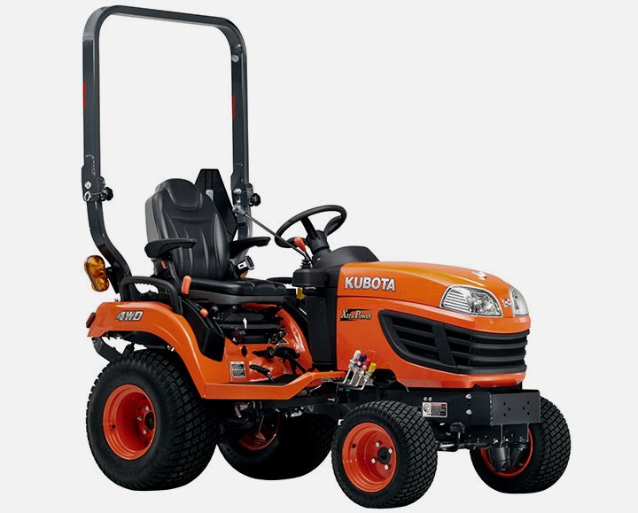 BX2370
 BX23S
BX23S BX25 TLB
 BX2660
 BX2680
 F3680
F3680 L175
L175 L185
L185 L210
L210 L225
L225 L235
L235 L245
L245 L260
L260 L275
L275 L285
L285 L305
L305 GR2120
 L1501
L1501 L2350
L2350 L2550
L2550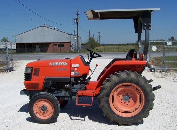 L2800
L2800 L3010
L3010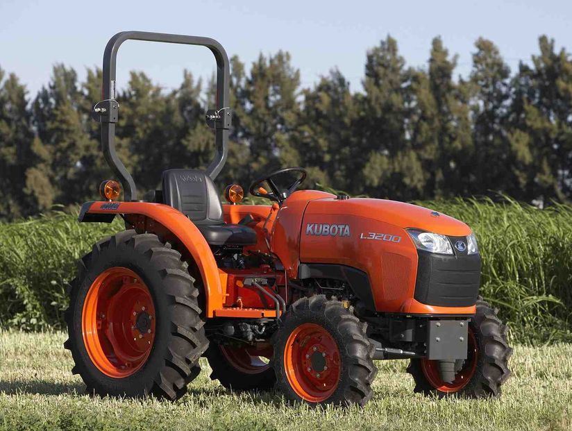 L3200HST
 L3301
L3301 L3560
L3560 L3800
L3800 L4701
L4701 L5740
L5740 M5-091
 M5-111
 M6060
M6060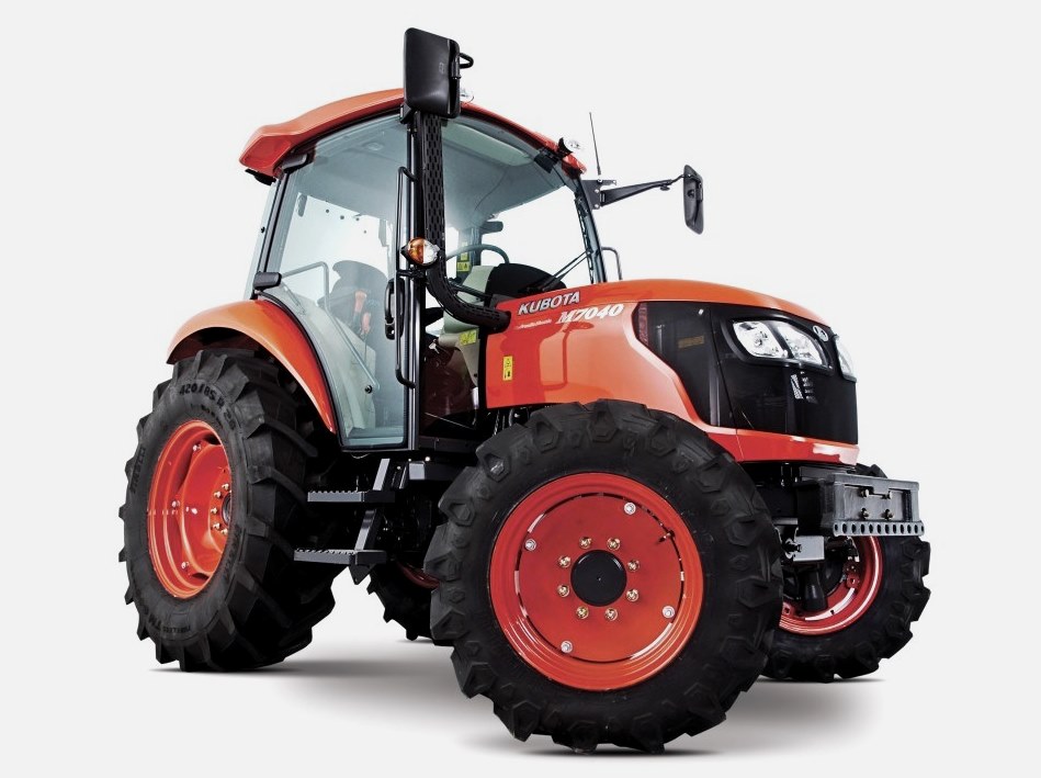 M7040
M7040 M9540
M9540 M9960
M9960 MX5100
 D662
D662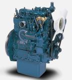 D722
D722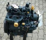 D750
D750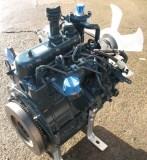 D782
D782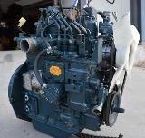 D850
D850 D902
D902 D905
D905 D950
D950 D1005
D1005 D1100
D1100 D1105
D1105 D1503
D1503 D1703
D1703 D1803
D1803 V1200
V1200 V1205
V1205 V1305
V1305 V1505
V1505 V2203
V2203 V2403
V2403 Z482
Z482 Z602
Z602 Z750
Z750 Z1100
Z1100 Z1300
Z1300 B1630
B1630 BF400
BF400 BF400G
 LA181
LA181 LA203
LA203 LA211
LA211 LA243
LA243 LA271
LA271 LA272
LA272 LA301
LA301 LA302
LA302 LA304
LA304 LA340
LA340 LA344
LA344 LA351
LA351 LA352
LA352 LA364
LA364 LA401
LA401 LA402
LA402 LA434
LA434 LA463
LA463 LA481
LA481 LA482
LA482 LA504
LA504 LA513
LA513 LA514
LA514 LA524
LA524 LA525
LA525 LA534
LA534 LA555
LA555 LA680
LA680 LA681
LA681 LA682
LA682 LA703
LA703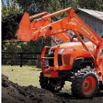 LA714
LA714 LA723
LA723 LA724
LA724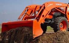 LA764
LA764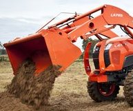 LA765
LA765 LA805
LA805 LA844
LA844 LA852
LA852 LA853
LA853 LA854
LA854 LA1002
 LA1055
 LA1065
 LA1153
 LA1154
 LA1251
 LA1301S
 LA1353
 LA1403
 LA1601S
 LA1854
 LA1944
 LA1953
 LA2253
 LM2605