________________________________________________________________________________
Kubota L1200 Front End Loader
Kubota L1200 Loader - Assembly Instructions
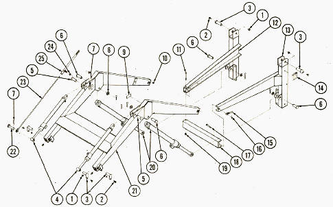
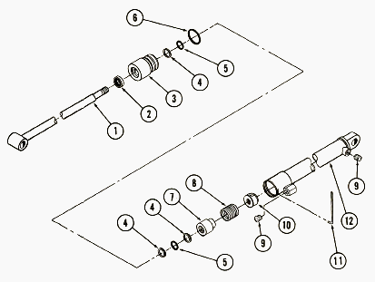
Kubota L1200 Loader Main Assembly: 1 - Lock Nut
(3/8-16), 2 - Serrated Machine Screw (3/8-16х1"), 3 - Pin (3-3/8), 4 -
Bucket Cylinder, 5 - Pin (1x2-1/8), 6 - Pin (1x2-7/8), 7 - Cotter Pin
(1/4x1-1/2), 8 - Washer Bushing, 9 - Decal, 10 - Grease Fitting
(1/4-28), 11 - Cap Screw (1/2-13x4-3/4), 12 - Right Side Frame, 13 -
Left Side Frame, 14 - Caution Decal, 15 - Handle Nut (7/16-14), 16 -
Cotter Pin (1/8x1”), 17 - Bolt (7/16-14x3-1/4), 18 - Bumper, 19 - Lock
Nut (1/2-13), 20 - Lift Cylinder, 21 - Boom, 22 - Pin (1x3-5/8), 23 -
Bucket Indicator Rod, 24 - Lock Nut (3/8-16), 25 - Bucket Indicator
Guide Tube
Installing mountings and hoses
Install mounting brackets and hoses on the tractor according to
instructions packed with mounting kits.
Installing side frames
Using a hoist locate the side frames (12, 13) over the mounting
brackets. Using hardware from mounting kit secure side frame as
specified in instructions packed with mounting kit.
Installing bucket attachment
Attach bucket to boom (21) and bucket cylinders (4) with 1”x3-3/8 pins
(3). Push lock taps flush against bucket ears, align the holes and
secure with 3/8x1” serrated machine screws (2) and lock nuts (1).
Installing bucket level indicator
Attach guide tube (25) to the right outside bucket cylinder ear on boom
(21) with 3/8 lock nuts. Leave lock nuts loose enough so guide tube
rotates freely. Slide rod (23) into guide tube. Pin rod (23) to bucket
and bucket cylinder with pin (22) and 1/4x1-1/2 cotter pin. Locate
tractor and loader on a level surface. Level the bottom of bucket on the
level surface and with bucket level cut off the excess rod (23) flush
with the end of guide tube (25).
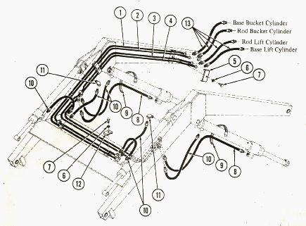
Hydraulic System: 1 - Oil Line (BBC), 2 - Oil Line
(RBC), 3 - Oil Line (RLC), 4 - Oil Line (BLC), 5 - Tube Clamp, 6 - Lock
Washer (3/8), 7 - Cap Screw (3/8-24x1”), 8 - Hose (3/8x38), 9 - Hose
Clamp, 10 - Hose (3/8x19), 11 - Street Elbow (3/8x90), 12 - Tube Clamp,
13 - Hose (3/8x30)
Kubota L1200 Loader - Hydraulic cylinder
repair
Cylinder disassembly procedure
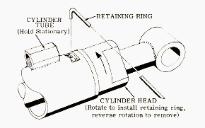
1. To remove the retaining ring: Hold the cylinder tube stationary and
turn the cylinder head until the beveled end of the retaining ring is
visible in the slot in the cylinder tube. Turn the cylinder head in the
proper direction to cause the beveled end of the retaining ring to catch
the slot edge, and thread out through the slot (If necessary, use a pipe
wrench on the cylinder head). If the piston assembly is removed intact
from the double acting bucket cylinders, the V-packing on the piston
will probably be damaged by the retaining ring groove in the cylinder
tube. Step 2 is the recommended procedure for removing the piston rod
assembly from the 1-3/4” double acting bucket cylinder without damaging
the V-packings on the piston.
2. To relieve compression on the V-packings of the double acting
cylinder to prevent damaging them: With the piston rod pushed all the
way in, rotate the rod end until the hole in the compression nut is
visible through the cylinder port. Insert a metal shaft (bolt or pin
punch) through the oil port and into the hole as shown in Figure.
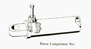
With the compression nut held stationary by the metal shaft, turn the
piston rod out approximately four turns, to relieve compression on the
piston V-packing. Remove the metal shaft and pull rod assembly out until
piston strikes the cylinder head. Slide the cylinder head out of the
cylinder tube. Carefully pull the piston assembly to a position where
the rear edge of the piston just protrudes from the cylinder tube. Turn
the piston rod to thread it completely out of the compression nut, and
pull the rod out. If the V-packing is to be replaced, the whole assembly
can be removed at one time. Carefully remove the piston. Leave the
V-packing and the compression nut in the cylinder. Carefully remove the
V-packings, one at a time.
3. Completely disassembly the piston and cylinder head. Remove all
internal seals and packings, and clean all the parts in a suitable
solvent. Discard and replace all damaged or worn parts. Inspect the
cylinder tube for rust. If the tube is scored and the score mark cannot
be removed with light buffing with honing paper, the tube must be
replaced.
Kubota L1200 Loader - Installing repair parts
in bucket cylinder
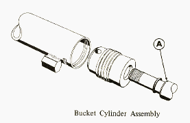
Double acting bucket cylinder: 1 - Shaft Assembly, 2 -
Wiper Seal, 3 - Cylinder Head, 4 - Back-Up Washer, 5 - O-Ring, 6 -
O-Ring, 7 - Piston, 8 - V-Pack, 9 - Caplug, 10 - Compression Nut, 11 -
Wire Retaining Ring, 12 - Cylinder Tube
Install wiper seal (2), back-up washer (4) and O-rings (5) into cylinder
head (3). Install O-ring (6) on outside of head. Remove the sharp edge
on the outside diameter of the piston end of the piston rod (A).
Lubricate the wiper seal, leather washer and O-ring in the cylinder head
with hydraulic oil and carefully slide the cylinder head onto the piston
rod. The piston V-packing set (8) must be installed on piston (7) so
that the lips of the packing face toward the rod end of the cylinder.
Lubricate the V-packing with hydraulic oil and slide them onto the
piston. Lubricate the O-ring and the leather washers (4 and 5) and
insert one leather washer and one O-ring into the piston (7). Carefully
slide the piston onto the cylinder rod. Thread the compression nut (10)
onto the end of the piston rod. Do not tighten the nut. Lubricate the
V-packing on the piston and the large O-ring on the cylinder head with
hydraulic oil and slide the piston rod assembly all the way into the
cylinder tube. Insert a metal shaft through the oil port in the cylinder
tube and into the hole in the compression nut. Turn the piston rod
tightly into the compression nut. Turn the cylinder head so that the
hole in the retaining ring groove appears in the slot in the cylinder
tube. Insert the hook-end of the retaining ring into the hole and turn
the cylinder head to thread the retaining ring into the groove.
Kubota L1200 Loader - Installing repair parts
in lift cylinder
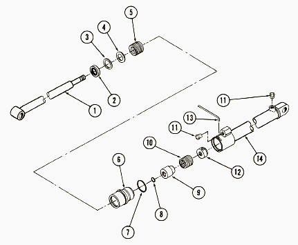
Double acting lift cylinder: 1 - Cylinder Shaft, 2 -
Wiper Seal, 3 - Snap Ring, 4 - Reinforcement Washer, 5 - V-Pack, 6 -
Cylinder Head, 7 - O-Ring, 8 - O-Ring, 9 - Piston, 10 - V-Pack, 11 -
Caplug, 12 - Piston Compression Nut, 13 - Wire Retaining Ring, 14 -
Cylinder Tube
Remove the sharp edge on the outside diameter of the piston end of the
piston rod. Place a new V-packing set (5) in the cylinder head (6) with
the lips on the packing facing inward. Place the reinforcement washer
(4) on the V-packing, and force down firmly, below snap ring groove.
Install the snap ring (3), with the rounded outer edge facing down, in
the groove. Make sure that it is firmly seated. Install the new wiper
seal (2) on the snap ring with the lip of the seal facing out, and flush
with the edge of the cylinder head. Place a new O-ring (7) in the groove
around the outside of the cylinder head. Lubricate the V-packing and
wiper seal and carefully slide the cylinder head onto the piston rod.
The V-packing set must be installed so the lips of the packing face
toward the rod end of the cylinder when installed on the piston.
Lubricate the V-packing (10) with hydraulic oil and slide them onto the
piston (9). Lubricate the small O-ring (8) with hydraulic oil and
carefully slide it over the threaded end of the piston rod. Place the
piston on the rod against the small O-ring. Thread the compression nut
(12) onto the end of the piston rod (1). Do not tighten the nut.
Lubricate the cylinder head and O-ring (6 and 7) and the piston and
V-packing (9 and 10) and slide the assembly all the way into the
cylinder tube. Insert a metal shaft through the oil port in the cylinder
tube and into the hole in compression nut. Turn the piston rod tightly
into the compression nut.
Turn the cylinder head so that the hole in the retaining ring groove
appears in the slot in the cylinder tube. Insert the hook-end of the
retaining ring into the hole and turn the cylinder head to thread the
retaining ring into the groove.
________________________________________________________________________________
________________________________________________________________________________
 SPECIFICATIONS
 LOADERS
 ENGINES
 MAINTENANCE
 PROBLEMS
________________________________________________________________________________________
| KUBOTA TRACTORS SPECIFICATIONS |
 B1241
B1241 B1600
B1600 B1700
B1700 B1750
B1750 B21 Backhoe
________________________________________________________________________________________
 B2150
B2150 B2301
B2301 B2320
B2320 B2530
B2530 B26 Backhoe
________________________________________________________________________________________
 B2601
B2601 B2650HSD
 B3030
B3030 B3350
B3350 B6000
B6000________________________________________________________________________________________
 B6100
B6100 B6200
B6200 B7000
B7000 B7001
B7001 B7100HST
________________________________________________________________________________________
 B7200
B7200 B7500
B7500 B7510
B7510 B7800
B7800 B8200HST
________________________________________________________________________________________
 BX1880
 BX2200
 BX2230
 BX2350
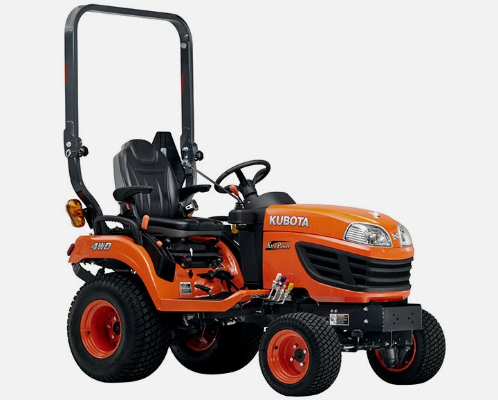 BX2370
________________________________________________________________________________________
 BX23S
BX23S BX25 TLB
 BX2660
 BX2680
 F3680
F3680________________________________________________________________________________________
 L175
L175 L185
L185 L210
L210 L225
L225 L235
L235________________________________________________________________________________________
 L245
L245 L260
L260 L275
L275 L285
L285 L305
L305________________________________________________________________________________________
 GR2120
 L1501
L1501 L2350
L2350 L2550
L2550 L2800
L2800________________________________________________________________________________________
 L3010
L3010 L3200HST
 L3301
L3301 L3400
L3400 L3560
L3560________________________________________________________________________________________
 L3800
L3800 L4701
L4701 L5740
L5740 M5-091
 M5-111
________________________________________________________________________________________
 M6060
M6060 M7040
M7040 M9540
M9540 M9960
M9960 MX5100
________________________________________________________________________________________
| KUBOTA ENGINES DATA AND SERVICE SPECS |
 D662
D662 D722
D722 D750
D750 D782
D782 D850
D850________________________________________________________________________________________
 D902
D902 D905
D905 D950
D950 D1005
D1005 D1100
D1100________________________________________________________________________________________
 D1105
D1105 D1503
D1503 D1703
D1703 D1803
D1803 V1200
V1200________________________________________________________________________________________
 V1205
V1205 V1305
V1305 V1505
V1505 V2203
V2203 V2403
V2403________________________________________________________________________________________
 Z482
Z482 Z602
Z602 Z750
Z750 Z1100
Z1100 Z1300
Z1300________________________________________________________________________________________
| KUBOTA FRONT END LOADERS |
 B1630
B1630 BF400
BF400 BF400G
 LA181
LA181 LA203
LA203________________________________________________________________________________________
 LA211
LA211 LA243
LA243 LA271
LA271 LA272
LA272 LA301
LA301________________________________________________________________________________________
 LA302
LA302 LA304
LA304 LA340
LA340 LA344
LA344 LA351
LA351________________________________________________________________________________________
 LA352
LA352 LA364
LA364 LA401
LA401 LA402
LA402 LA403
LA403________________________________________________________________________________________
 LA434
LA434 LA463
LA463 LA481
LA481 LA482
LA482 LA504
LA504________________________________________________________________________________________
 LA513
LA513 LA514
LA514 LA524
LA524 LA525
LA525 LA534
LA534________________________________________________________________________________________
 LA555
LA555 LA680
LA680 LA681
LA681 LA682
LA682 LA703
LA703________________________________________________________________________________________
 LA714
LA714 LA723
LA723 LA724
LA724 LA764
LA764 LA765
LA765________________________________________________________________________________________
 LA805
LA805 LA844
LA844 LA852
LA852 LA853
LA853 LA854
LA854________________________________________________________________________________________
 LA1002
 LA1055
 LA1065
 LA1153
 LA1154
________________________________________________________________________________________
 LA1251
 LA1301S
 LA1353
 LA1403
 LA1601S
________________________________________________________________________________________
 LA1854
 LA1944
 LA1953
 LA2253
 LM2605
________________________________________________________________________________________
| KUBOTA TRACTORS TROUBLESHOOTING | ||||
| L235 | L2501 | L2550 | L275 | L3110 |
| L3301 | L35 | L3710 | L3901 | L4310 |
| L5030 | M4700 | M5700 | M6040 | M6800 |
| M8200 | M8540 | M9000 | MX5100 | MX5200 |