________________________________________________________________________________
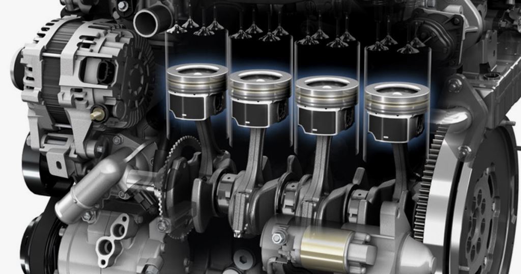
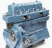
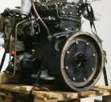
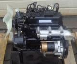
Perkins 4.248 Engine
Perkins 4.248 Engine Specifications
Engine Model ........ A4.248
Engine Type ........ Four Stroke, direct injection diesel
Nominal Bore, in (mm) ........ 3.975 (100,96)
Stroke, in (mm) ........ 5,0 (127,0)
Cycle ........ Four Stroke
No. of Cylinders ........ 4
Cylinder Arrangement ........ In-Line
Cubic Capacity, cu.in (L) ........ 248 (4,06)
Maximum Power Rating, kW (Hp) ........ 62,0 (84,0)
Nominal Power Rating, kW (Hp) ........ 59,0 (80,0)
Rated Engine Speed, rpm ........ 2500
Maximum Torque, Nm (Ibf-ft) ........ 263 (194)
Torque Speed, prm ........ 1400
Compression Ratio ........ 15.5:1
Induction System ........ Naturally aspirated
Direction of Engine Rotation ........ Clockwise from the Front
Firing Order ........ 1-3-4-2
Fuel System
Fuel Injection Pump Make ........ CAV
Fuel Injection Pump Type ........ DPA
Injection Pump Rotation ........ Clockwise
Injection Pump Plunger Dia ........ 8,5 mm
Combustion System ........ Direct Injection
Fuel Lift Pump Type ........ A.C. Delco. V.P. Series
Fuel Lift Pump Method of Drive ........ Eccentric on Camshaft
Fuel Filter Element Type ........ Paper
Fuel Filter Valve Type ........ Gravity Vent Valve
Lubricating System
Relief Valve Type ........ Spring loaded plunger
Pressure Setting ........ 5,86 bar
Oil Pump Type ........ Rotor type
Lubricating Oil Filter Type ........ Full Flow
Dimensions
Width, in (mm) ........ 27.96 (710)
Height, in (mm) ........ 30.51 (775)
Depth, in (mm) ........ 20.95 (532)
Weight, lbs (kg) ........ 750 (340)
Perkins 4.248 Maintenance Data
Engine oil type ........ SAE 10W-30/15W-40
Engine oil capacity, L (qts) ........ 8.0 (8.4)
Coolant capacity, L (qts) ........ 15.6 (16.5)
Oil filter change interval ........ Every 250 hours
Oil change interval ........ Every 250 hours
Fuel filter change interval ........ Every 500 hours
Perkins 4.248 Service Specifications
Wear Limits
Cylinder Head Bow Wear Limit (Transverse), in (mm) ........ 0,003 (0,08)
Cylinder Head Bow Wear Limit (Longitudinal), in (mm) 0,006 (0,15)
Cylinder Head Maximum Bore Wear Limit, in (mm) ........ 0,008 (0,2)
Crankshaft Main and Big End Journal Wear Ovality, in (mm) ........ 0,0015 (0,04)
Maximum Crankshaft End Float Wear Limit, in (mm) ........ 0,015 (0,38)
Valve Stem to Bore/Guide Clearance (inlet), in (mm) ........ 0,005 (0,13)
Valve Stem to Bore/Guide Clearance (exhaust), in (mm) ........ 0,006 (0,15)
Valve Head Thickness Between Run-out of Valve Seat and Face of Valve, in (mm) ........ 0,0312 (0,79)
Rocker Clearance on Rocker Shaft, in (mm) ........ 0,005 (0,13)
Camshaft Journals (Ovality and Wear), in (mm) ........ 0,002 (0,05)
Camshaft End Float, in (mm) ........ 0,020 (0,51)
Idler Gear End Float, in (mm) ........ 0,010 (0,25)
Valve Head Depth below Cylinder Head Face (exhaust, earlier), in (mm) ........ 0,055 (1,40)
Valve Head Depth below Cylinder Head Face (exhaust, current), in (mm) ........ 0,073 (1,85)
Valve Head Depth below Cylinder Head Face (inlet), in (mm) ........ 0,061 (1,55)
Cylinder Block
Total Height of Cylinder Block between Top and Bottom Faces, in (mm) ........ 17,367-17,375 (441,12-441,33)
Parent Bore Diameter for Cylinder Liner (Chrome Thin Wall), in (mm) ........ 3,9325-3,9635 (100,65-100,67)
Parent Bore Diameter for Cylinder Liner (Chrome Thick Wall), in (mm) ........ 4,0625-4,0635 (103,19-103,22)
Parent Bore Diameter for Flangeless Cylinder Liner (Cast Iron), in (mm) ........ 4,0615-4,0625 (103,16-103,19)
Parent Bore Diameter for Flanged Cylinder Liner (Cast Iron), in (mm) ........ 4,1025-4,1035 (104,20-104,23)
Depth of Recess for Liner Flange (Cast Iron), in (mm) ........ 0,150-0,154 (3,81-3,91)
Depth of Recess for Liner Flange (Chrome Thin Wall) early type, in (mm) ........ 0,046-0,049 (1,17-1,25)
Depth of Recess for Liner Flange (Chrome Thin Wall) later type, in (mm) ........ 0,049-0,051 (1,25-1,30)
Depth of Recess for Liner Flange (Chrome Thick Wall, in (mm) ........ 0,150-0,152 (3,81-3,86)
Main Bearing Parent Bore Diameter, in (mm) ........ 3,166-3,167 (80,42-80,44)
Camshaft Bore Diameter No. 1 for Bush (where fitted), in (mm) ........ 2,1875-2,1887 (55,56-55,59)
Camshaft Bearing Bush Internal Diameter fitted, in (mm) ........ 2,0000-2,0017 (50,8-50,84)
Camshaft Bore Diameter No. 1, in (mm) ........ 2,000-2,001 (50,80-50,83)
Camshaft Bore Diameter No. 2, in (mm) ........ 1,990-1,9918 (50,55-50,59)
Camshaft Bore Diameter No. 3, in (mm) ........ 1,970-1,9718 (50,04-50,08)
Cylinder Liners
Cylinder Liner O.D. (Flangeless), in (mm) ........ 4,0660-4,0670 (103,27-103,30)
Cylinder Liner O.D. (Flanged), in (mm) ........ 4,1045-4,1055 (104,25-104,28)
Cylinder Liner O.D. (Non-Flame Ring), in (mm) ........ 4,1045-4,1055 (104,25-104,28)
Flanged Pre-Finished Service Liner O.D., in (mm) ........ 4,1025-4,1035 (104,20-104,23)
Flanged Pre-Finished Service Liner O.D. (non-Flame Ring), in (mm) ........ 4,1025-4,1035 (104,20-104,23)
Interference Fit Liner in Cylinder Block (Flangeless), in (mm) ........ 0,003-0,005 (0,08-0,13)
Interference Fit Liner in Cylinder Block (Flanged), in (mm) ........ 0,001-0,003 (0,03-0,08)
Interference Fit Liner in Cylinder Block (Non-Flame Ring), in (mm) ........ 0,001-0,003 (0,03-0,38)
Transition Fit of Pre-Finished Service Liner, in (mm) ........ 0,001 (0,03)
Finished Bore Diameter of Production Liners, in (mm) ........ 3,9785-3,9795 (101,05-101,07)
Bore Diameter of Pre-Finished Service Liner in Block, in (mm) ........ 3,980-3,981 (101,09-101,12)
Height of Top of Liners above Cylinder Block Face, in (mm) ........ 0,028-0,037 (0,71-0,94)
Flange Thickness of Liner, in (mm) ........ 0,150-0,152 (3,81-3,86)
Relationship of Liner Flange to Cylinder Block Face, in (mm) ........ 0,002 (0,03) Above to 0,004 (0,10) Below
Overall Length of Liner (Flangeless), in (mm) ........ 8,805-8,815 (223,65-223,90)
Perkins A4.248 Cylinder Head
Cylinder Head Length, in (mm) ........ 19,875 (504,82)
Cylinder Head Depth, in (mm) ........ 4,0625 ± 0,015 (103,20 ± 0,38)
Skimming allowance on Cylinder Head Face, in (mm) ........ 0,012 (0,30)
Minimum Cylinder Head Depth after Skimming, in (mm) ........ 4,0355 (102,51)
Maximum Nozzle Protrusion after Skimming, in (mm) ........ 0,175 (4,44)
Leak Test Pressure ........ 2,06 bar
Valve Seat Angle ........ 45 deg
Valve Bore in Cylinder Head, in (mm) ........ 0,37425-0,37525 (9,51-9,53)
Valve Guide Parent Bore Diameter, in (mm) ........ 0,6247-0,6257 (15,87-15,89)
Clearances between Valve Stem and Rocker Lever, in (mm) ........ 0,012 (0,30)
Inner Valve Springs Fitted Length, in (mm) ........ 1,5625 (39,7)
Outer Valve Springs Fitted Length, in (mm) ........ 1,780 (45,22)
Valve Guides
Inside Diameter (Inlet and Exhaust), in (mm) ........ 0,375-0,376 (9,53-9,55)
Outside Diameter, in (mm) ........ 0,6259-0,6265 (15,89-15,91)
Interference Fit of Guide in Cylinder Head Bore, in (mm) ........ 0,0002-0,0018 (0,005-0,046)
Depth of Counterbore (Exhaust Guide), in (mm) ........ 0,4062 (10,32)
Overall Length of Guide (Exhaust), in (mm) ........ 2,4375 (61,92)
Overall Length of Guide (Inlet), in (mm) ........ 2,281 (57,94)
Guide Protrusion Above Cylinder Head Top Face, in (mm) ........ 0,594 (15,09)
Exhaust Valves
Valve Stem Diameter, in (mm) ........ 0,372-0,3728 (9,45-9,47)
Clearance Fit of Valve in Guide (if fitted), in (mm) ........ 0,00225-0,004 (0,06-0,10)
Clearance Fit of Valve in Head, in (mm) ........ 0,00145-0,00325 (0,04-0,08)
Valve Head Diameter, in (mm) ........ 1,435-1,445 (36,45-36,70)
Valve Face Angle ........ 45 deg
Valve Head Depth below Cylinder Head Face (earlier), in (mm) ........ 0,029-0,039 (0,74-0,99)
Valve Head Depth Below Cylinder Head Face (current), in (mm) ........ 0,047-0,057 (1,19-1,45)
Overall Length of Valve, in (mm) ........ 4,847-4,863 (123,11-123,52)
Service Valve Stem Oversizes, in (mm) ........ 0,003; 0,015 and 0,030 (0,08; 0,38 and 0,76)
Inlet Valves
Valve Stem Diameter, in (mm) ........ 0,3725-0,3735 (9,46-9,48)
Clearance Fit of Valve in Guide (if fitted), in (mm) ........ 0,0015-0,0035 (0,04-0,09)
Clearance Fit of Valve in Head, in (mm) ........ 0,00075-0,00275 (0,02-0,07)
Valve Head Diameter, in (mm) ........ 1,736-1,746 (44,09-44,36)
Valve Face Angle ........ 45 deg
Valve Head Depth Below Cylinder Head Face, in (mm) ........ 0,035-0,045 (0,89-1,14)
Overall Length of Valve, in (mm) ........ 4,831-4,847 (122,71-123,11)
Service Valve Stem Oversizes, in (mm) ........ 0,003; 0,015 and 0,030 (0,08; 0,38 and 0,76)
Tappets
Overall Length, in (mm) ........ 2,96875 (75,41)
Outside Diameter Tappet Shank, in (mm) ........ 0,7475-0,7485 (18,99-19,01)
Cylinder Block Tappet Bore Diameter, in (mm) ........ 0,750-0,7513 (19,05-19,08)
Tappet Running Clearance in Bore, in (mm) ........ 0,0015-0,0038 (0,04-0,10)
Outside Diameter of Tappet Foot, in (mm) ........ 1,1875 (30,16)
Rocker Shaft and Rocker Levers
Overall Length of Shaft, in (mm) ........ 16,796 (426,62)
Outside Diameter of Shaft, in (mm) ........ 0,7485-0,7495 (19,01-19,04)
Inside Diameter of Lever Bore, in (mm) ........ 0,7505-0,7520 (19,06-19,10)
Lever Clearance on Rocker Shaft, in (mm) ........ 0,001-0,0035 (0,03-0,09)
Pistons (4 Rings)
Pistons Type ........ Cavity Crown
Piston Height in relation to Cylinder Block, in (mm) ........ 0,002-0,010 (0,05-0,26) above
Bore Diameter for Gudgeon Pin, in (mm) ........ 1,37485-1,37505 (34,92-34,93)
Compression Ring Groove Width (Numbers 1, 2 and 3), in (mm) ........ 0,0957-0,0967 (2,43-2,46)
Scraper Ring Groove Width (Number 4, Plain piston), in (mm) ........ 0,2525-0,2535 (6,41-6,44)
Scraper Ring Groove Width (No.4, Inserted piston), in (mm) ........ 0,189-0,190 (4,80-4,83)
Pistons (3 Rings)
Pistons Type ........ Cavity Crown
Piston Height in Relation to Cylinder Block Top Face, in (mm) ........ 0,002-0,010 (0,05-0,26) above
Bore Diameter for Gudgeon Pin, in (mm) ........ 1,37485-1,37505 (34,92-34,93)
Compression Ring Groove Width (Numbers 1 and 2), in (mm) ........ 0,1015-0,1024 (2,58-2,60)
Scraper Ring Groove Width (No. 3), in (mm) ........ 0,1984-0,1992 (5,04-5,06)
Piston Rings (4 Rings)
Top Compression Ring ........ Chrome Insert, Parallel Face/Barrel Face
2nd and 3rd Compression Rings ........ Internally Stepped
4th Scraper Ring ........ Spring Loaded Conformable
Compression Ring Width, in (mm) ........ 0,0928/0,0938 (2,36/2,38)
Ring Clearance Groove (Numbers 1, 2 and 3), in (mm) ........ 0,0019/0,0039 (0,05/0,10)
Ring Gap, Chrome, in (mm) ........ 0,016/0,034 (0,41/0,86)
Ring Gap, Cast Iron, in (mm) ........ 0,012/0,030 (0,30/0,76)
Ring Gap, Scraper, in (mm) ........ 0,012/0,036 (0,30/0,91) varies according to type
Piston Rings (3 Rings)
Top Compression Ring ........ Molybdenum Faced, Internally Stepped, Barrel Faced
Second Compression Ring ........ Internally Stepped, Taper Faced
Third Scraper Ring ........ Chrome Faced, Spring Loaded Conformable
Compression Ring Width (Number 1 and 2), in (mm) ........ 0,097/0,098 (2,46/2,49)
Compression Ring Clearance Groove (Number 1 and 2), in (mm) ........ 0,0017/0,0027 (0,04/0,07)
Scraper Ring Width, in (mm) ........ 0,1954/0,1964 (4,96/4,99)
Scraper Ring Clearance Groove, in (mm) ........ 0,002/0,0038 (0,05/0,10)
Ring Gap, Number 1, in (mm) ........ 0,016/0,034 (0,41/0,86)
Ring Gap, Number 2, in (mm) ........ 0,016/0,034 (0,41/0,86)
Ring Gap, Number 3, in (mm) ........ 0,016/0,034 (0,41/0,86)
Small End Bush
Type ........ Steel Backed, Lead Bronze Lined
Outside Diameter of Small End Bush, in (mm) ........ 1,535-1,5365 (38,99-39,03)
Length of Small End Bush, in (mm) ........ 1,316-1,336 (33,43-33,93)
Inside Diameter before Reaming, in (mm) ........ 1,359-1,363 (34,52-34,62)
Inside Diameter after Reaming, in (mm) ........ 1,37575-1,3765 (34,94-34,96)
Clearance between Small End Bush and Gudgeon Pin, in (mm) ........ 0,00075-0,0017 (0,019-0,043)
Connecting Rod
Type ........ H-Section
Cap Location to Connecting Rod ........ Serrations
Big End Parent Bore Diameter, in (mm) ........ 2,6460-2,6465 (67,21-67,22)
Small End Parent Bore Diameter, in (mm) ........ 1,53125-1,53225 (38,90-38,92)
Length from Centre Line of Big End to Centre Line of Small End, in (mm) ........ 8,624-8,626 (219,05-219,10)
Length from Centre Line of Big End to Centre Line of Big End, Width, in (mm) ........ 1,577-1,580 (40,06-40,13)
Perkins 4.248 Crankshaft
Overall Length, in (mm) ........ 24,01-24,04 (609,85-610,62)
Main Journal Diameter, in (mm) ........ 2,9984-2,9992 (76,16-76,18)
Main Journal Length (No. 1), in (mm) ........ 1,453-1,473 (36,91-37,41)
Main Journal Length (No. 2, 4 and 5), in (mm) ........ 1,545-1,549 (39,24-39,34)
Main Journal Length (No. 3), in (mm) ........ 1,738-1,741 (44,15-44,22)
Crankpin Diameter, in (mm) ........ 2,4988-2,4996 (63,47-63,49)
Crankpin Length, in (mm) ........ 1,5885-1,5915 (40,35-40,42)
Surface Finish (All Journals), micro in (microns) ........ 16 (0,4) maximum
Main Journal and Crankpin Regrind Undersizes, in (mm) ........ -0,010, 0,020 and 0,030 (-0,25, 0,51 and 0,76)
Oil Seal Helix Diameter (rope seals only), in (mm) ........ 3,124-3,125 (79,35-79,38)
Oil Seal Helix Width, in (mm) ........ 0,050-0,080 (1,27-2,03)
Oil Seal Helix Depth, in (mm) ........ 0,004-0,008 (0,10-0,20)
Flange Diameter, in (mm) ........ 5,247-5,249 (133,27-133,32)
Spigot Bearing Recess Depth, in (mm) ........ 0,781 (19,84)
Spigot Bearing Recess Bore, in (mm) ........ 1,8497-1,8502 (46,98-47,00)
Crankshaft End Float, in (mm) ........ 0,002-0,015 (0,05-0,38)
Crankshaft Thrust Washers
Type ........ Steel Backed, Aluminium Tor Lead Bronze Faced
Position in Engine ........ Centre Main Bearing
Thrust Washer Thickness (STD), in (mm) ........ 0,089-0,091 (2,26-2,31)
Thrust Washer Thickness (O/S), in (mm) ........ 0,096-0,099 (2,44-2,51)
Thrust Washer Outside Diameter, in (mm) ........ 4,088-4,098 (103,84-104,90)
Thrust Washer Inside Diameter, in (mm) ........ 3,420-3,430 (86,87-87,12)
Main Bearings
Type ........ Pre-Finished, Steel Backed, Aluminium Tor Lead Bronze Faced
Shell Width (No. 1, 2, 4, and 5), in (mm) ........ 1,245-1,255 (31,62-31,88)
Shell Width (No. 3), in (mm) ........ 1,435-1,445 (36,45-36,70)
Outside Diameter of Main Bearing, in (mm) ........ 3,167 (80,41)
Inside Diameter of Main Bearing, in (mm) ........ 3,0010-3,0026 (76,23-76,27)
Main Bearing Running Clearance, in (mm) ........ 0,0018-0,0042 (0,05-0,11)
Shell Thickness, in (mm) ........ 0,0822-0,0825 (2,088-2,098)
Connecting Rod Bearings
Type ........ Pre-Finished, Steel Backed, Aluminium Tor Lead Bronze Faced
Shell Width, in (mm) ........ 1,245-1,255 (31,62-31,88)
Outside Diameter of Connecting Rod Bearing, in (mm) ........ 2,6465 (67,22)
Inside Diameter of Connecting Rod Bearing, in (mm) ........ 2,5008-2,5019 (63,52-63,55)
Connecting Rod Bearing Running Clearance, in (mm) ........ 0,0012-0,0031 (0,03-0,08)
Shell Thickness, in (mm) ........ 0,0723-0,0726 (1,836-1,844)
Perkins 4.248 Camshaft
Journal Diameter (Number 1), in (mm) ........ 1,9965-1,9975 (50,71-50,74)
Cylinder Block Camshaft Bore Diameter (Number 1), in (mm) ........ 2,000-2,001 (50,8-50,83)
Journal Running Clearance (Number 1), in (mm) ........ 0,0025-0,0045 (0,06-0,11)
Journal Diameter (Number 2), in (mm) ........ 1,9865-1,9875 (50,46-50,48)
Cylinder Block Camshaft Bore Diameter (Number 2), in (mm) ........ 1,990-1,992 (50,55-50,60)
Journal Running Clearance (Number 2), in (mm) ........ 0,0025-0,0053 (0,06-0,14)
Journal Diameter (Number 3), in (mm) ........ 1,9665-1,9675 (49,95-49,98)
Cylinder Block Camshaft Bore Diameter (Number 3), in (mm) ........ 1,970-1,972 (50,04-50,09)
Journal Running Clearance (Number 3), in (mm) ........ 0,0025-0,0053 (0,06-0,14)
Cam Lift, in (mm) ........ 0,300-0,303 (7,62-7,70)
Oilways for Rocker Shaft Lubrication, in (mm) ........ No.2 Journal
Camshaft Thrust Washer
Type ........ 360 degrees
Thrust Washer Outside Diameter, in (mm) ........ 2,872-2,874 (72,95-73,00)
Cylinder Block Recess Diameter for Thrust Washer, in (mm) ........ 2,875-2,885 (73,03-73,28)
Clearance Fit of Washer in Recess, in (mm) ........ 0,001-0,013 (0,03-0,33)
Thrust Washer Inside Diameter, in (mm) ........ 1,75 (44,45)
Thrust Washer Thickness, in (mm) ........ 0,216-0,218 (5,47-5,54)
Cylinder Block Recess Depth for Thrust Washer (Early), in (mm) ........ 0,152-0,154 (3,86-3,91)
Cylinder Block Recess Depth for Thrust Washer (Later), in (mm) ........ 0,187-0,190 (4,75-4,83)
Cylinder Block Recess Depth for Thrust Washer (Current), in (mm) ........ 0,215-0,218 (5,46-5,53)
Thrust Washer Protrusion beyond Cylinder Block Front Face (Early), in (mm) ........ 0,062-0,066 (1,53-1,68)
Thrust Washer Protrusion beyond Cylinder Block Front Face (Later), in (mm) ........ 0,026-0,031 (0,66-0,79)
Thrust Washer Relationship to Cylinder Block Front Face (Current), in (mm) ........ -0,002-+0,003 (-0,05-+0,07)
Camshaft End Float, in (mm) ........ 0,004-0,016 (0,10-0,41)
Lubricating System
Relief Valve Length of Plunger Outside Diameter of Plunger, in (mm) ........ 0,826 (20,98)
Relief Valve Inside Diameter of Valve Housing Bore, in (mm) ........ 0,5585-0,5595 (14,186-14,211)
Relief Valve Clearance of Plunger in Bore Outside Diameter of Spring, in (mm) ........ 0,570 (14,5)
Oil Capacity (Standard) ........ 8.4 qts (8 litres)
Cooling System
Engine Water Capacity (Less Radiator) ........ 9.7 qts (9.36 litres)
Thermostat Type ........ Bellows or Wax
Opening Temperature Fully ........ 170-180 F (77-83C)
Water Pump Type ........ Centrifugal
Water Pump Outside Diameter of Shaft for Pulley, in (mm) ........ 0,7492-0,7497 (19,03-19,04)
Water Pump Inside Diameter of Pulley Bore, in (mm) ........ 0,7508-0,7516 (19,07-19,0)
Water Pump Clearance Fit of Pulley on Shaft, in (mm) ........ 0,0011-0,0024 (0,03-0,06)
Water Pump Outside Diameter of Shaft for Impeller, in (mm) ........ 0,6262-0,6267 (15,90-15,92)
Water Pump Inside Diameter of Impeller Bore, in (mm) ........ 0,6249-0,6257 (15,87-15,89)
Perkins 4.248 Tightening Torque Specs
Cylinder Head Nuts/Setscrews (1/2 in), Nm (Ibf-ft) ........ 136 (100)
Cylinder Head Setscrews with Integral Head, Nm (Ibf-ft) ........ 120 (88)
Connecting Rod Nuts, Nm (Ibf-ft) ........ 122 (90)
Main Bearing Setscrews, Nm (Ibf-ft) ........ 244 (180)
Idler Gear Hub Setscrews, Nm (Ibf-ft) ........ 41 (30)
Fuel Injection Pump Gear Retaining Setscrews, Nm (Ibf-ft) ........ 27 (20)
D.P.S. Fuel Injection Pump Gear Retaining Nut, Nm (Ibf-ft) ........ 81 (60)
Flywheel Setscrews, Nm (Ibf-ft) ........ 108 (80)
Flywheel Place Bolts, Nm (Ibf-ft) ........ 122 (90)
Flywheel Housing Setscrews (Standard), Nm (Ibf-ft) ........ 49 (36)
Camshaft Gear Retaining Setscrews, Nm (Ibf-ft) ........ 68 (50)
Crankshaft Pulley Retaining Setscrew, Nm (Ibf-ft) ........ 406 (300)
Oil Filter Setscrews/Nuts, Nm (Ibf-ft) ........ 41 (30)
Atomiser Securing Nuts, Nm (Ibf-ft) ........ 18 (14)
Atomiser Clamp Nuts, Nm (Ibf-ft) ........ 12 (9)
Rockershaft Support Brackets (Cast Iron), Nm (Ibf-ft) ........ 74 (54)
High Pressure Fuel Pipe Nuts, Nm (Ibf-ft) ........ 20 (15)
Dynamo Pulley Retaining Nut, Nm (Ibf-ft) ........ 27 (20)
Alternator Pulley Retaining Nut, Nm (Ibf-ft) ........ 41 (30)
Balancer Retaining Setscrews, Nm (Ibf-ft) ........ 50 (40)
________________________________________________________________________________________
 Perkins A4.212
 Perkins AD3.152
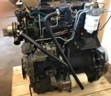 Perkins 4.236
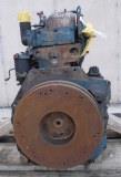 Perkins F3.144
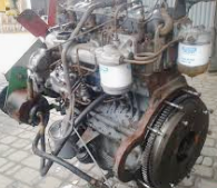 Perkins 4.154
________________________________________________________________________________
________________________________________________________________________________________
| DIESEL ENGINES SPECS AND SERVICE DATA |
________________________________________________________________________________________
 Perkins 4.108
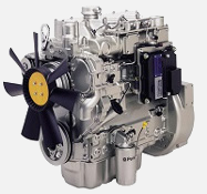 Perkins 1004.42
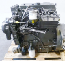 Perkins 1004.4T
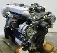 Perkins 1004.40T
________________________________________________________________________________________
 Perkins 1004.4
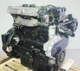 Perkins 1004.40
 Perkins 1006.6T
 Perkins 1006.60T
 Perkins 1006.6
________________________________________________________________________________________
 Yanmar 3TNA72
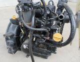 Yanmar 3TNE68
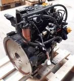 Yanmar 3TNE74
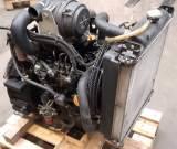 Yanmar 3TNV70
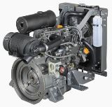 Yanmar 3TNV76
________________________________________________________________________________________
________________________________________________________________________________________
 Yanmar 3TNV82A
 Yanmar 3TNV88
 Yanmar 4TNE84
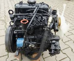 Mitsubishi_K3E
 Mitsubishi_S3L
________________________________________________________________________________________
 Kubota D902
 Kubota D905
 Kubota D950
 Kubota D1005
 Kubota D1100
________________________________________________________________________________________
 Kubota D1105
 Kubota D1503
 Kubota D1703
 Kubota D1803
 Kubota V1200
________________________________________________________________________________________
 Kubota V1205
 Kubota V1305
 Kubota V1505
 Kubota V2203
 Kubota V2403
________________________________________________________________________________________
| GASOLINE ENGINES SPECS AND SERVICE DATA |
 CH12.5
 CH14S
CH14S CH15S
CH15S CH16
CH16 CH18S
CH18S________________________________________________________________________________________
 CH23S
CH23S CH25S
CH25S CH640S
 CH730S
 CH750S
________________________________________________________________________________________
 CV740S
 K161
K161 K181
K181 K241
K241 K301
K301________________________________________________________________________________________
 K321
K321 K341
K341 K361
K361 M18
M18 M20
M20________________________________________________________________________________________
 SV470S
 SV530S
 SV540S
 SV590S
 SV600S
________________________________________________________________________________________
 FA210
FA210 FA210D
 FB460V
 FC150V
 FC290V
________________________________________________________________________________________
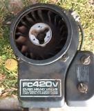 FC420V
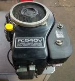 FC540V
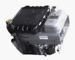 FD501V
 FD590V
 FD620D
________________________________________________________________________________________
 FD731V
 FD750D
 FH430V
 FH500V
 FH531V
________________________________________________________________________________________
 FH580V
 FH601V
 FH680V
 FS541V
 FS600V
________________________________________________________________________________________
 FS651V
 FX651V
 FX691V
 FX730V
________________________________________________________________________________________