________________________________________________________________________________
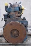
Perkins F3.144 Engine (Fordson Dexta)
General Technical Data
Perkins F3.144 Engine Specifications
Engine Model ...................... Ford-Perkins F3.144
Engine Type ...................... Vertical, 3 cylinder direct injection
diesel
Number of Cylinders ...................... 3, in-line
Displacement, cu in (L) ...................... 144.0 (2.40)
Engine Bore, in (mm) ...................... 3.5 (89.0)
Engine Stroke, in (mm) ...................... 5.0 (127.0)
Aspiration ...................... Natural
Rated Engine Power, hp (kW) ...................... 32.0 (23.9)
Rated Engine Speed, rpm ...................... 2000
Maximum Torque, Nm (ft-lbs) ...................... 126 (93)
Torque Speed, rpm ...................... 1200
Compression ...................... 16.5:1
Firing Order ...................... 1-2-3
Electrical System Rating, Volts ...................... 12
Fuel System
Fuel System ...................... Direct injection
Fuel Lift Pump Type ...................... Diaphragm with hand primer.
Fuel Filter Type ...................... Replaceable paper element
Air Cleaner Type ...................... Oil bath
Fuel Injection Pump Type ...................... Enclosed camshaft with
pneumatic governor
Camshaft Rotation ...................... Clockwise from drive end
Governor Type ...................... Pneumatic
Fuel Tank Capacity, gal (L) ...................... 8.4 (31.8)
Lubrication System
Lubrication System Type ...................... Under pressure, forced
feed type
Oil Filter Type ...................... Full flow, pressure relief,
replaceable element
Oil Pump ...................... Rotor type
Cooling System
Cooling System Type ...................... Pressure
Water Pump ...................... Centrifugal type
Fan ...................... 2/4 blades
Thermostat ...................... Controlled with by-pass
Perkins F3.144 Maintenance Data
Fuel type ...................... Diesel fuel No. 2-D
Engine oil type ...................... SAE 5W/20W
Engine oil capacity, qts (L) ...................... 7.7 (7.2)
Coolant capacity, qts (L) ...................... 9.0 (8.5)
Oil filter replacement interval ...................... Every 200 hours
Oil change interval ...................... Every 200 hours
Fuel filter replacement interval ...................... Every 300 hours
Fordson Dexta Engine Service Specifications
Cylinder Liners
Method of retention ...................... Interference fit
Amount of interference, in (mm) ...................... 0.002-0.004
(0.051-0.102)
Outside diameter bore in cylinder block, in (mm) ......................
3.6895-3.6905 (93.637-93.663)
Internal diameter (before finish boring), in (mm) ......................
3.478-3.482 (88.341-88.443)
Diameter of finished bore (standard), in (mm) ......................
3.501-3.502 (88.925-88.951)
Diameter of finished bore 0.030 in (0.762 mm) o/s, in (mm) ........
3.531-3.532 (89.687-89.713)
Pistons
Piston Type ...................... High silicon, aluminium alloy
Piston diameter at bottom of skirt at 90 deg. to piston pin, in (mm)
.... 3.4964-3.4974 (88.808-88.834)
Piston diameter at bottom of skirt in line with piston pin, in (mm)
....... 3.4944-3.4962 (88.758-88.803)
Piston oversizes, in (mm) ...................... 0.030 (0.762)
Diameter of piston pin bore, in (mm) ......................
1.2495-1.2500 (31.737-31.750)
Piston Rings
Top compression ring type ...................... Cast iron, chrome plate
Second compression ring type ...................... Cast iron, plain
faced
Third compression ring type ...................... Laminated spring
steel rings
Top oil control ring type ...................... Laminated spring steel
rings
Lower oil control ring type ...................... Cast iron, slotted
Top compression ring groove width, in (mm) ......................
0.0957-0.0967 (0.243-0.246)
Second compression ring groove width, in (mm) ......................
0.0957-0.0967 (0.243-0.246)
Third compression ring groove width, in (mm) ......................
0.127-0.128 (0.323-0.325)
Top oil control ring groove width, in (mm) ......................
0.252-0.253 (0.640-0.643)
Lower oil control ring groove width, in (mm) ......................
0.252-0.253 (0.640-0.643)
Top compression ring width, in (mm) ...................... 0.0928-0.0938
(0.236-0.238)
Second compression ring width, in (mm) ......................
0.0928-0.0938 (0.236-0.238)
Third compression ring width, in (mm) ...................... 0.03125
(0.794) Nominal
Lower oil control ring width, in (mm) ...................... 0.249-0.250
(0.632-0.635)
Top compression ring groove clearance, in (mm) ......................
0.0019-0.0039 (0.048-0.099)
Second compression ring groove clearance, in (mm) ......................
0.0019-0.0039 (0.048-0.099)
Lower oil control ring groove clearance, in (mm) ......................
0.002-0.004 (0.051-0.102)
Top compression ring gap, in (mm) ...................... 0.010-0.015
(0.254-0.381)
Second compression ring gap, in (mm) ...................... 0.009-0.013
(0.229-0.330)
Third compression ring gap, in (mm) ...................... 0.008-0.010
(0.203-0.254)
Top oil control ring gap, in (mm) ...................... 0.018-0.037
(0.457-0.940)
Lower oil control ring gap, in (mm) ...................... 0.009-0.013
(0.229-0.330)
Piston Pins
Piston pin type ...................... Fully floating
Length, in (mm) ...................... 2.961-2.965 (75.2 to 75.3)
Outside diameter, in (mm) ...................... 1.24975-1.2500
(31.744-31.75)
Clearance in piston, in (mm) ...................... 0.00025-0.0005
(0.0064-0.0127)
Clearance in small end bore, in (mm) ......................
0.0005-0.00175 (0.0127-0.0445)
Method of retention ...................... End circlips
Cylinder Head and Valves
Valve clearance (inlet and exhaust), in (mm) ......................
0.010 (0.254)
Valve head diameter (inlet), in (mm) ...................... 1.532-1.536
(38.913-39.014)
Valve head diameter (exhaust), in (mm) ......................
1.313-1.317 (33.350-33.452)
Valve stem diameter (inlet and exhaust), in (mm) ......................
0.311-0.312 (7.899-7.925)
Valve length (inlet and exhaust), in (mm) ......................
4.486-4.514 (113.95-114.66)
Angle of valve head, degrees ...................... 45
Angle of valve seat in cylinder head, degrees ...................... 44
Length of valve guide, in (mm) ...................... 2.59275-2.59475
(65.856-65.997)
Valve guide internal diameter, in (mm) ......................
0.314-0.3155 (7.976-8.014)
Valve guide outside diameter, in (mm) ......................
0.5005-0.501 (12.713-12.72)
Stem to guide clearance, in (mm) ...................... 0.002-0.0045
(0.051-0.114)
Valve depth in cylinder head (new), in (mm) ......................
0.059-0.087 (1498-2.210)
Valve depth in cylinder head (max), in (mm) ...................... 0.140
(3.556)
Free length of valve spring (Inner), in (mm) ......................
1.365-1.405 (34.671-35.687)
Free length of valve spring (Outer), in (mm) ......................
1.783-1.803 (45.288-45.796)
Inlet valve timing opens, degrees ...................... 13 before
T.D.C.
Inlet valve timing closes, degrees ...................... 43 after
B.D.C.
Exhaust valve timing opens, degrees ...................... 46 before
B.D.C.
Exhaust valve timing closes, degrees ...................... 10 after
T.D.C.
Diameter of tappet stem, in (mm) ...................... 0.62225-0,62375
(15.805-15.843)
Tappet to cylinder head clearance, in (mm) ......................
0.00075-0,0035 (0.019-0.089)
Rocker shaft length, in (mm) - 12.235-12.265 (310.77-311.53)
Rocker shaft diameter, in (mm) ...................... 0.62225-0.62375
(15.805-15.843)
Clearance between rocker arm and shaft, in (mm) ......................
0.00075-0.0035 (0.019-0.089)
Connecting Rod
Length between centres, in (mm) ...................... 8.999-9.001
(228.575-228.625)
Big end bore (without liners), in (mm) ......................
2.3950-2.3955 (60.833-60.846)
Big end bore (with liners), in (mm) ...................... 2.251-2.252
(57.175-57.201)
Undersizes of liners, in (mm) ...................... 0.010 (0.254),
0.020 (0.508), 0.030 (0.762)
Connecting rod big end width, in (mm) ......................
1.5502-1.5525 (39.375-39.434)
Liner thickness (standard), in (mm) ......................
0.07175-0.0720 (1.822-1.829)
Clearance on crankpin, in (mm) ...................... 0.002-0.0035
(0.051-0.089)
End-float on crankpin, in (mm) ...................... 0.0095-0.0133
(0.241-0.338)
Small end bore (with bush), in (mm) ...................... 1.2505-1.2515
(31.763-31.788)
Clearance between small end and piston pin, in (mm) ................
0.0005-0.00175 (0.0127-0.0445)
Crankshaft and Main Bearings
Crankpin journal length, in (mm) ...................... 1.5620-1.5635
(39.675-39.713)
Crankpin journal diameter, in (mm) ...................... 2.2485-2.249
(57.112-57.125)
Crankshaft end-float, in (mm) ...................... 0.00225-0.01025
(0.0572-0.2604)
Rear main bearing thrust washer thickness, in (mm)
...................... 0.123-0.125 (3.124-3.175)
Main bearing liner thickness (standard), in (mm) ......................
0.08225-0.0825 (2.089-2.096)
Undersizes, in (mm) ...................... 0.010 (0.254), 0.020 (0.508),
0.030 (0.762)
Main bearing journal diameter, in (mm) ......................
2.7485-2.749 (69.812-69.825)
Main bearing journal clearance, in (mm) ......................
0.0025-0.0045 (0.064-0.114)
Number of teeth on crankshaft gear ...................... 25
Effective diameter of crankshaft pulley, in (mm) ......................
5.21875 (132.556)
Crankshaft pulley fit, in (mm) ...................... 0.00025-0.00175
(0.0064-0.0445)
Crankshaft gear fit, in (mm) ...................... 0.001 (0.025)
Idler Gear
Number of teeth on idler gear ...................... 90
Internal diameter of gear, in (mm) ...................... 2.125-2.1266
(53.975-54.016)
Diameter of idler gear spigot, in (mm) ......................
2.123-2.1238 (53.924-53.945)
Clearance between gear and spigot, in (mm) ......................
0.0012-0.0036 (0.030-0.091)
Camshaft
Camshaft drive ...................... Gear
Maximum cam lift, in (mm) ...................... 0.30955-0.31555
(7.863-8.015)
Maximum valve lift, in (mm) ...................... 0.348 (8.84)
Journal diameter front, in (mm) ...................... 1.869-1.870
(47.473-47.498)
Journal diameter centre, in (mm) ...................... 1.859-1.860
(47.219-47.244)
Journal diameter rear, in (mm) ...................... 1.839-1.840
(46.711-46.736)
Bearing clearance, in (mm) ...................... 0.004-0.008
(0.102-0.203)
Number of teeth on camshaft gear ...................... 50
Backlash (all timing gears), in (mm) ...................... 0.003-0.006
(0.076-0.152)
Flywheel
Flywheel outside diameter, in (mm) ...................... 15.5 (393.7)
Flywheel run-out clutch face (max T.I.R.), in (mm)
...................... 0.001 (0.025)
Flywheel run-out outside diameter (max T.I.R.), in (mm)
...................... 0.012 (0.305)
Method of flywheel retention ...................... Spigot and six
set-screws
Number of teeth on starter ring gear ...................... 122
Method of starter ring gear retention ...................... 6
cross-headed screws
Fuel System
Fuel pump plunger stroke/diameter, in (mm) ......................
0.277/0.237 (7.0/6.0)
Lubrication ...................... Self-lubricating after initial
filling
Camshaft end-float, in (mm) ...................... 0.002-0.006
(0.051-0.152)
Camshaft end-float shims, in (mm) ...................... 0.004/0.008
(0.1/0.2)
Phasing tolerance, deg ...................... 1 (pump) between elements
Plunger head clearance, in (mm) ...................... 0.031-0.051
(0.8-1.3)
Plunger arm shims, in (mm) ...................... 0.009 (0.229)
Fuel tnjector number of spray holes ...................... 2
Fuel tnjector diameter of spray holes, in (mm) ......................
0.013 (0.35)
Back leak test ........ Tune for pressure to fall from 125 to 90 bar
should be between 6 sec, and 45 sec
Injector pipes inner diameter, in (mm) ...................... 0.06
(1.50)
Injector pipes outer diameter, in (mm) ......................
0.233-0.238 (5.9-6.06)
Governor maximum speed under load, rpm ...................... 2000
Governor idling speed, rpm ...................... 550-600
Lubrication System
Oil pump shaft diameter, in (mm) ...................... 0.498-0.4985
(12.649-12.662)
Diameter of shaft bore in pump housing, in (mm) ......................
0.500-0.501 (12.700-12.725)
Oil pump shaft clearance, in (mm) ...................... 0.0015-0.003
(0.038-0.076)
Idler gear shaft diameter, in (mm) ......................
0.65475-0.65535 (16.631-16.646)
Idler gear bush internal diameter, in (mm) ......................
0.6562-0.6572 (16.667-16.693)
Oil pump shaft clearance, in (mm) ...................... 0.00085-0.00245
(0.022-0.062)
Fit of idler gear shaft in pump body, in (mm) ......................
0.00025-0.00185 (0.0064-0.047)
Clearance between drive rotor and driven rotor, in (mm)
...................... 0.006 (0.152)
Clearance between drive rotor and body, in (mm) ......................
0.010 (0.254)
End-float of rotors ...................... 0.003 (0.076)
Cooling System
Fan diameter (up to 90F/32.2С), in (mm) ...................... 15 (381),
2 blade
Fan diameter (above 90F/32.2С), in (mm) ...................... 15 (381),
4 blade
Water pump shaft bearing fit in pump body, in (mm)
...................... 0.0001-0.0011 (0.0025-0.0279)
Water pump clearance between impeller blades and body, in (mm) .......
0.005-0.020 (0.127-0.508)
Pump shaft fit in impeller bore, in (mm) ......................
0.00045-0.0017 (0.0114-0.0432)
Pump pulley fit on pump shaft, in (mm) ......................
0.0015-0.0028 (0.0381-0.0711)
Thermostat (Opening temperature), F (C) ...................... 56-65
(73.9-68.8)
Thermostat (Fully open temperature) ...................... 85 (85)
Perkins F3.144 Tightening Torque Specs
Cylinder head nuts, lb-ft (Nm) ...................... 55-60 (74.8-81.6)
Main bearing cap bolts, lb-ft (Nm) ...................... 90-95
(122.4-129.2)
Big end cap nuts (Cadmium plated), lb-ft (Nm) ......................
50-55 (68-74.8)
Big end cap nuts (Uplated), lb-ft (Nm) ...................... 65-70
(88.4-95.2)
Flywheel bolts, lb-ft (Nm) ...................... 75 (101.9)
Delivery valve holders, lb-ft (Nm) ...................... 30 (40.8)
Fuel pump drive gear adaptor retaining nut, lb-ft (Nm)
...................... 45 (61.2)
Oil filter for centre bolt, lb-ft (Nm) ...................... 10 (13.6)
Nozzle nut, lb-ft (Nm) ...................... 60-75 (81.6-101.9)
 Perkins 4.248
 Perkins A4.212
 Perkins AD3.152
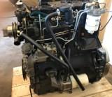 Perkins 4.236
________________________________________________________________________________
| DIESEL ENGINES SPECS AND SERVICE DATA |
________________________________________________________________________________________
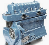 Perkins 4.108
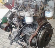 Perkins 4.154
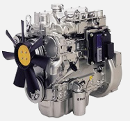 Perkins 1004.42
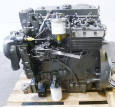 Perkins 1004.4T
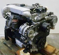 Perkins 1004.40T
________________________________________________________________________________________
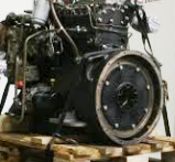 Perkins 1004.4
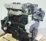 Perkins 1004.40
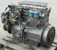 Perkins 1006.6T
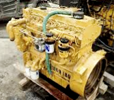 Perkins 1006.60T
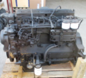 Perkins 1006.6
________________________________________________________________________________________
_______________________________________________________________________________________
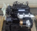 Yanmar 3TNA72
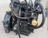 Yanmar 3TNE68
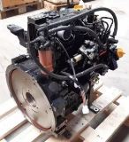 Yanmar 3TNE74
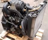 Yanmar 3TNV70
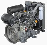 Yanmar 3TNV76
________________________________________________________________________________________
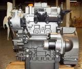 Yanmar 3TNV82A
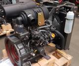 Yanmar 3TNV88
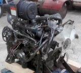 Yanmar 4TNE84
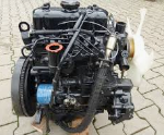 Mitsubishi_K3E
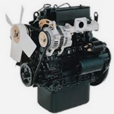 Mitsubishi_S3L
________________________________________________________________________________________
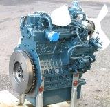 Kubota D902
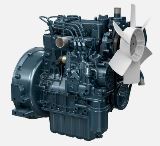 Kubota D905
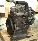 Kubota D950
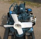 Kubota D1005
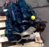 Kubota D1100
________________________________________________________________________________________
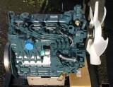 Kubota D1105
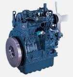 Kubota D1503
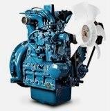 Kubota D1703
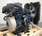 Kubota D1803
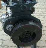 Kubota V1200
________________________________________________________________________________________
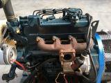 Kubota V1205
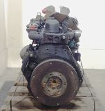 Kubota V1305
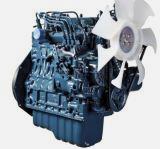 Kubota V1505
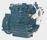 Kubota V2203
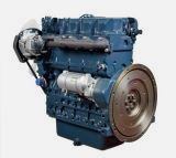 Kubota V2403
________________________________________________________________________________________
| GASOLINE ENGINES SPECS AND SERVICE DATA |
 CH12.5
 CH14S
 CH15S
 CH16
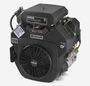 CH18S
________________________________________________________________________________________
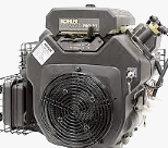 CH23S
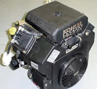 CH25S
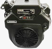 CH640S
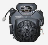 CH730S
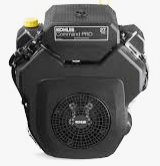 CH750S
________________________________________________________________________________________
 CV740S
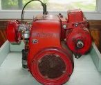 K161
 K181
 K241
 K301
________________________________________________________________________________________
 K321
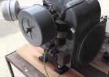 K341
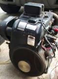 K361
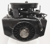 M18
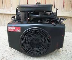 M20
________________________________________________________________________________________
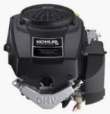 SV470S
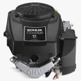 SV530S
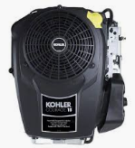 SV540S
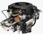 SV590S
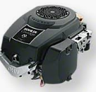 SV600S
________________________________________________________________________________________
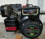 FA210
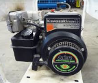 FA210D
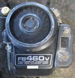 FB460V
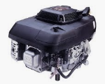 FC150V
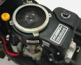 FC290V
________________________________________________________________________________________
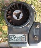 FC420V
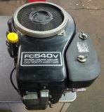 FC540V
 FD501V
 FD590V
 FD620D
________________________________________________________________________________________
 FD731V
 FD750D
 FH430V
 FH500V
 FH531V
________________________________________________________________________________________
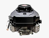 FH580V
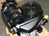 FH601V
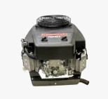 FH680V
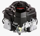 FS541V
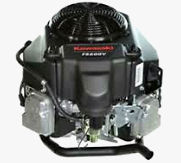 FS600V
________________________________________________________________________________________
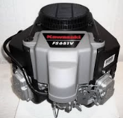 FS651V
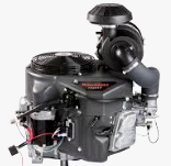 FX651V
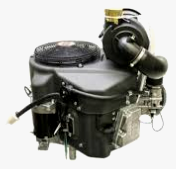 FX691V
 FX730V
________________________________________________________________________________________