________________________________________________________________________________
Borg and Beck Continuous Clutch
Case IH Tractor 385/485/585/685 Borg
and Beck Continuous Clutch Assembly
Before removing clutch, mark pressure plate to flywheel position for
reassembly. Place an 11 mm nut under each release lever to relieve
spring tension as clutch mounting bolts are removed. Remove pressure
plate assembly and outer clutch disc from flywheel.
Identify flywheel side of clutch discs, if not already marked I to
assure correct reassembly. Make alignment marks on separator plate and
flywheel for reassembly, then remove separator plate and inner disc.
Remove the three springs from flywheel.
Scribe alignment marks on clutch pressure plate, inner cover and outer
cover and release levers to pressure plate lugs for reassembly in
original positions.
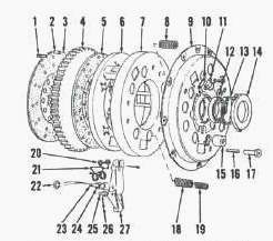
Fig.17. Case Tractor Borg and Beck continuous clutch showing
component parts and their relative positions
Remove release lever actuating plate (14). Remove the three adjusting
screws (16). Place three Code 14 spacers (from clutch tool kit) on
912917 base plate. Position pressure plate on base plate so pressure
plate rests on top of spacers. Install a 912724 spacer under and a stud
through each mounting hole in clutch cover.
Thread studs into base plate, install flat washers and nuts on studs and
tighten nuts evenly until clutch cover contacts spacers. Release the
large release lever springs (21) from clutch cover tabs. Remove pivot
pins (25) and release levers (27).
Remove springs (20 and 21), pivot pin (23) and needle bearing (24) from
release levers. Loosen stud nuts evenly until clutch spring tension is
relieved, then separate pressure plate components.
Remove snap ring (13) and tap bearing (12) from outer cover. Check
release levers for wear on tips of fulcrum points and renew as needed.
Check all clutch springs and renew if distorted, discolored or weak.
Inspect pressure plate for cracks, scoring or discoloration. Light
scores may be removed by resurfacing, however maximum amount of material
removed must not exceed 0.38 mm (0.015 inch).
If separator plate shows wear only on transmission side, further use may
be obtained by reversing the plate. If plate is badly scored or cracked,
it may be resurfaced providing amount of material removed does not
exceed 0.76 mm (0.030 inch) total for both sides. Plate thickness when
new is 17,78-17.90 mm (0.700-0.705 inch).
Make certain separator plate is a free sliding fit in flywheel teeth. A
tight plate can cause PTO clutch slippage. A very loose plate may rattle
when clutch pedal is depressed, however separator plate rattle does not
affect clutch operation.
Install pressure plate into inner and outer covers and check side
clearance between the three pressure plate lugs and their respective
slots in covers. Side clearance should be 0,15-0.30 mm (5-0.012 inch).
If slots are excessively worn, renew covers.
Inspect Case IH Tractor 385/485/585/685 clutch release bearing and renew
if excessively worn or damaged.
To reassemble, position pressure plate on 912917 base plate so the Code
14 spacers are located below the release lever lugs, Place clutch inner
cover (7) over pressure plate aligning marks made during disassembly.
Install springs on inner cover, then place outer cover over the springs
and onto the studs and spacers aligning match marks on covers. Tighten
stud nuts evenly until outer cover contacts the spacers. Assemble
release levers and install in their original positions on pressure
plate.
Using clutch actuating tool or other suitable means, actuate release
levers several times to be certain clutch springs are properly seated.
Install 912723 adapter in center hole of base plate.
Assemble 961845 guide pin into adapter and position Code 8 spacer on
guide pin with recess side down. Install 961880 stud, 920203 gage and
961879 nut on the guide pin.
Hold gage down firmly, then check clearance between each release lever
and the gage. The levers must just touch gage or be within 0.05 mm
(0.002 inch) of gage. To adjust clearance, add or remove shims (10)
under roller pads (11).
A variation of 0.025 mm (0.001 inch) in shim thickness will change
release lever height approximately 0.114 mm (0.0045 inch). Adjust all
levers to as near equal height as possible. Remove lever adjusting gage.
Reconnect release lever springs (21) in tabs of outer cover. Install
adjusting screws (16), but do not adjust at this time. Place 11 mm (7/16
inch) nuts under each release lever, then remove nuts from base plate
studs. Remove Case IH Tractor clutch assembly from base plate. Install
release lever actuating plate (14).
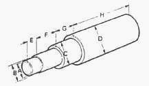
Fig.18. Borg and Beck continuous clutch, use a pilot shaft made
to dimensions shown
To reinstall clutch, place springs (1) in flywheel, then install inner
disc with large hub towards flywheel. Install separator plate aligning
marks on plate and flywheel made during removal. Install outer disc with
side stamped "Fly-wheel Side" facing flywheel.
Install pressure plate assembly aligning match marks made during
removal. Use a suitable pilot tool to align inner and outer discs, then
tighten clutch mounting bolts evenly to 68 N>m (50 ft.-lbs.) torque.
Using a feeler gage through holes in cover, check clearance between end
of adjusting screws and the pressure plate. Clearance should be 1.77 mm
(0.070 inch). Adjust the screws as required, then secure with locknuts.
________________________________________________________________________________
________________________________________________________________________________________
 CASE IH SPECS
 J.I. CASE SPECS
 PROBLEMS
 LOADERS
________________________________________________________________________________________
| CASE IH TRACTORS SPECIFICATIONS |
 FARMALL 110A
 FARMALL 120A
 FARMALL 30C
 FARMALL 75C
 MAGNUM 280
________________________________________________________________________________________
 580E Backhoe
 580L Backhoe
 580N Backhoe
 580 Super L
 580SM Backhoe
________________________________________________________________________________________
________________________________________________________________________________________
 580SLE Backhoe
 580SN Backhoe
 580M Backhoe
 580 Super E
 580ST Backhoe
________________________________________________________________________________________
 MAGNUM 310
 MAGNUM 340
 MAXXUM 110CVX
 MAXXUM 120CVX
 MAXXUM 125
________________________________________________________________________________________
 1394
1394 1455XL
 1494
1494 1594
1594 3230
3230________________________________________________________________________________________
 4210
4210 585XL
585XL 633
633 695XL
695XL 733
733________________________________________________________________________________________
 MX110
MX110 MX135
MX135 MX150
MX150 MXU110
 MXU135
________________________________________________________________________________________
 PUMA 175CVX
 PUMA 185CVX
 PUMA 200CVX
 PUMA 240CVX
 OPTUM 300
________________________________________________________________________________________
 FARMALL 50B
 FARMALL 95U
 FARMALL 125A
 PUMA 150
 PUMA 165
________________________________________________________________________________________
 MAGNUM 210
 MX 170
 MAXXUM 150
 OPTUM 270
 MAGNUM 315
________________________________________________________________________________________
 FARMALL 70
 FARMALL 75N
 FARMALL 95C
 FARMALL 105N
 FARMALL 30B
________________________________________________________________________________________
| CASE IH FRONT END LOADERS SPECS |
 L103 Loader
 L104 Loader
 L105 Loader
 L106 Loader
 L107 Loader
________________________________________________________________________________________
 L108 Loader
 L130 Loader
 L160 Loader
 L300 Loader
 L340 Loader
________________________________________________________________________________________
 L350 Loader
 L360 Loader
 L530 Loader
 L540 Loader
 L545 Loader
________________________________________________________________________________________
 L550 Loader
 L555 Loader
 L560 Loader
 L565 Loader
 L570 Loader
________________________________________________________________________________________
 L575 Loader
 L720 Loader
 L730 Loader
 L735 Loader
 L740 Loader
________________________________________________________________________________________
 LRZ 95
 LRZ 100
 LRZ 120
 LRZ 130
 LRZ 150
________________________________________________________________________________________
 L745 Loader
 L750 Loader
 L755 Loader
 L760 Loader
 L765 Loader
________________________________________________________________________________________
 L770 Loader
 L775 Loader
 L780 Loader
 L785 Loader
 L795 Loader
________________________________________________________________________________________
 90 Loader
 890 Loader
 2200 Loader
 2250 Loader
 LX156 Loader
________________________________________________________________________________________