________________________________________________________________________________
John Deere 5225, 5325, 5425, 5525, 5625 Drivetrain
- JD 5225-5625 Engine
- JD 5225-5625 PTO and Hitch
- JD 5225-5625 Drivetrain
- JD 5225-5625 Hydraulic System
JD 5225, 5325, 5425,
5525, 5625 Transmission
Operating SyncShuttle Transmission
Gear shift lever provides three forward travel speeds (1, 2, 3) and
reverse:
- Nine forward speeds are available when using range and gear shift
levers.
- Three reverse speeds are available when using the range shift lever.
Slow speed gearing (creeper) is available as an option. It provides a
fourth speed range. To prevent unnecessary wear, never "ride" the clutch
by resting a foot on
the pedal. Gear (1, 2, 3) and direction shifts (forward and reverse) can
be made on-the-go, without stopping. Release clutch pedal gradually to
take up load
smoothly.
Operating PowrReverser Transmission
Leaving transmission in gear with engine stopped will not prevent
tractor from moving. Put transmission gear shift lever in PARK and
electro-hydraulic directional
reverser lever in NEUTRAL before dismounting. Gear shift lever provides
four forward travel speeds (1, 2, 3, 4) and reverse. Range shift lever
provides three
speed ranges. Electro-hydraulic (EH) directional reverser lever provides
travel direction (forward or reverse). When using range and gear shift
levers in different
combinations, 12 forward and reverse speeds are available. Slow speed
gearing (creeper) is available as an option.
- When starting 5525, 5325, 5425, 5225, 5625 John Deere tractor, put EH
directional reverser lever in neutral and cycle clutch pedal one time to
disengage the
engagement override valve. To prevent unnecessary wear, never "ride" the
clutch by resting a foot on the pedal.
- Depress clutch pedal and stop tractor before shifting range shift
lever.
- Use EH directional reverser lever to select travel direction. You can
change travel direction without depressing the clutch pedal.
- Depress clutch pedal when shifting gears. Gear shifts (1, 2, 3, 4) can
be made on-the-go, without stopping. Release clutch pedal gradually to
take up load
smoothly.
The Neutral Indicator lights when gear shift lever and EH directional
reverser lever are both in neutral. The indicator light will go out when
the gear shift lever is put in
PARK. The indicator light will flash if the gear shift lever is in
Neutral and EH directional reverser lever is in forward or reverse. The
Information Indicator lights if a
malfunction is detected in the transmission.
Using Infinitely Variable Shuttle (If Equipped)
The Infinitely Variable Shuttle adjusts load take-up and acceleration
when making directional changes with EH directional reverser lever,
during repetitive cycle
work such as loader operation:
- In full left (counterclockwise) position (as shown), load take-up and
acceleration ramp-up are slow to respond.
- When operating with high load and ballast, turn control knob clockwise
to acceleration and load take-up response.
- Premature tire wear can occur when operating in full right (clockwise)
position on concrete or paved surfaces.
Creeper Gear Operation - A slow-speed creeper gear is available as an
option and provides slowest speed range. Moving the range shift lever to
optional creeper
(Snail) range provides greatly reduced ground speeds for special
operations. SyncShuttle transmission: Gear shift lever provides three
forward travel speeds and
reverse in the creeper range. PowrReverser transmission: Gear shift
lever provides four travel speeds in forward and reverse in the creeper
range.
Operating Brakes
- Before operating JD 5625, 5325, 5425, 5525, 5225 tractor on a road,
lock brake pedals together with locking bar. Use brakes lightly and
cautiously when slowing
from transport speed.
- Brake pedals shown in locked position.
- Use individual brakes to assist in making sharp turns. Disengage brake
pedal locking bar and depress only one brake pedal.
- To stop tractor, depress both brake pedals. To prevent unnecessary
wear, never ride the brakes by resting a foot on the pedals.
- Reduce speed if towed load weighs more than the tractor and is not
equipped with brakes. Avoid hard braking applications. Consult implement
operator's manual
for recommended transport speeds.
- Use additional caution when transporting towed loads under adverse
conditions, when turning or when stopping on inclines.
Differential Lock - Dont operate tractor at high speed or attempt to
turn with differential lock engaged. To prevent damage to drive train,
dont engage differential lock
when one wheel is spinning and the other is completely stopped. When one
wheel starts to lose traction, stop tractor and depress pedal to engage
differential lock.
Tractor wheels must be stopped or turning at the same speed before
engaging differential lock. If possible, engage differential lock before
entering conditions where
tires may slip. Unequal traction will keep the lock engaged. When
traction equalizes, lock will disengage itself by spring action. If lock
does not disengage, depress
one brake pedal and then the other. If tires repeatedly slip, then get
traction, then slip again, hold pedal down in the engaged position.
Checking Brakes
With engine stopped, check manual brakes for correct function:
- Disengage brake pedal locking bar.
- Pump left brake pedal, then right brake pedal. The pedals should have
a solid feel. If pedals do not feel solid, bleed the brakes.
- Check to make sure the pedals do not settle to the end of stroke
within 10 seconds after being applied. If leakage exceeds this rate or
if one pedal settles faster
than the other, see your service.
- Press both pedals simultaneously. A solid pedal should be obtained at
approximately the same pedal height on both pedals. If height varies
more than 51 mm (2
in.) bleed the brakes. Any noticeable pedal drift downward from the
point of resistance indicates brake leakage.
- A solid pedal and balance between the left and right pedals are
important for emergency braking conditions when the locking bar is
engaged.
Checking Transmission-Hydraulic System Oil Level
- Operate engine at approximately 1000 rpm for at least one minute.
- Stop engine and wait an additional three minutes before checking oil
level.
- 5225, 5325, 5425, 5525, 5625 John Deere tractor should be on level
ground, hitch in the lowered position, engine stopped and transmission
in park when checking
oil level.
- Oil temperature should be approximately 45C (113F). Sight glass
observations will be significantly higher with hotter oil temperatures
and lower with colder oil.
- Observe oil level in sight glasses at rear of tractor. Oil level
should appear at BOTTOM of site glass.
- Oil level below top sight glass can result in power loss and heat
generation during transport.
- If oil level is at TOP of site glass, remove filler cap and add
hydraulic oil.
Cleaning Transmission-Hydraulic Oil Pickup Screen
- Drain transmission-hydraulic oil. Remove two cap screws and pickup
screen cover.
- Remove pickup screen and inspect it for damage. Replace if necessary.
Clean screen in solvent and blow dry with compressed air.
- Inspect O-ring for damage. Replace if necessary.
- Carefully install screen so the front of screen is inserted in hole at
front of differential case.
- Install O-ring, cover and cap screws. Fill system with
transmission-hydraulic oil.
- Check oil level at sight glass after filling, and again after
operating for five minutes.
Checking and Adjusting Clutch Pedal Free Play (SyncShuttle Transmission)
Straddle Mount and Hi-Crop
- Measure distance from firewall-to-edge of clutch pedal arm.
- Depress clutch pedal (bold arrow) until resistance is felt and measure
same distance. The difference between the recorded measurements is
clutch pedal free
play. If free play is not within specification, adjust clutch linkage.
Free Play Distance - 21-25 mm (0.830-0.984 in.).
- Remove cover and clip pin. Loosen jam nut.
- Push and hold clutch lever forward until resistance is felt. Rotate
clevis in or out until clevis and clutch lever holes align.
- Move clevis away from clutch lever and rotate clevis counterclockwise
2-1/2 turns.
- Align clevis with clutch lever and install clip pin. Tighten jam nut
and install cover.
Cab and IOOS
- Measure distance from firewall-to-edge of clutch pedal arm. Depress
clutch pedal (bold arrow) until resistance is felt and measure same
distance.
- The difference between the recorded measurements is clutch pedal free
play. If free play is not within specification, adjust clutch linkage.
Free Play Distance - 21-25 mm (0.830-0.984 in.).
- Loosen jam nuts.
- Turn turnbuckle: Counterclockwise to increase free play / Clockwise to
decrease free play. Tighten jam nuts.
JD 5225, 5325, 5425, 5525, 5625 Front Axle and Wheels
Operating Mechanical Front Wheel Drive (Electro-Hydraulic Control)
Use mechanical front wheel drive (MFWD) as required for better traction.
Mechanical front wheel drive greatly increases traction, it does not
increase the stability of
the tractor. With MFWD engaged, the tractor can climb steeper slopes but
it does not become more stable. The possibility of a tip-over increases
with MFWD. Use
extra caution on slopes.
When driving on icy, wet, or graveled surfaces, reduce speed and
properly ballast tractor to avoid skidding and loss of steering control.
For best control under
adverse conditions, engage mechanical front wheel drive (if equipped).
To extend tire life, engage mechanical front wheel drive only when
needed. Dont engage
when driving on hard surfaces. Dont install tire chains on tractor front
wheels. Chains will strike and damage tractor.
MFWD can be engaged and disengaged in all ranges and gears (forward and
reverse) during operation, and under full load.
- Depress top end of switch to engage MFWD. Indicator will light when
MFWD is engaged.
- Depress bottom end of switch to disengage MFWD.
Mechanical Front Wheel Drive (Electro-Hydraulic Control with Auto Engage
and Brake Assist)
Use AUTO or BRAKE ASSIST positions when transporting tractor, not full
time ON mode. MFWD indicator lights whenever front wheel drive is
engaged. MFWD
can be engaged and disengaged in all gears (forward and reverse) during
operation and under full load.
Switch has three operating positions:
- Center ON position engages MFWD full time.
- Top AUTO position disengages MFWD automatically when either brake
pedal is pressed or if speed exceeds 14 km/h (8.6 mph). MFWD
automatically re-engages when brakes are released and speed is below 14 km/h (8.6 mph).
- Bottom BRAKE ASSIST position engages MFWD when BOTH brake pedals are
depressed.
Towing 5525, 5325, 5425, 5225, 5625 John Deere Tractor
Remove MFWD drive shaft if towing tractor with front wheels on a
carrier. Loss of electrical power or transmission-hydraulic system
pressure will engage the
MFWD and pull tractor off the carrier, even with switch in the
DISENGAGED position. To avoid transmission and drive train component
damage, NEVER attempt
to start tractor by towing; engine will not start.
- If equipped with MFWD and towing tractor with front wheels on a
carrier, remove drive shaft: 1) Remove three cap screws and slide drive
shaft shield away from
drop housing. Repeat on opposite end. 2) Remove spring pin using a punch
and hammer. 3) Support drive shaft and slide coupler toward drop
housing. 4) Remove
drive shaft, shields and couplers.
- Check transmission-hydraulic oil level (it must be visible in the top
sight glass). Add 1L (1qt) for each 90 mm (3-1/2 in.) front wheels are
raised off the ground.
Dont raise wheels more than 305 mm (12 in.). Drain excess oil after
transporting.
- Tap brake pedals to make sure differential lock is not engaged.
Disengage PTO and move range and gear shift levers to NEUTRAL.
- PowrReverser Transmission: Move EH directional reverser lever to
NEUTRAL.
- If possible, operate engine above 1250 rpm to provide lubrication,
power steering, and power brakes. Have an operator steer and brake
tractor.
- Do not tow a tractor faster than 8 km/h (5 mph). Do not exceed 3 km/h
(2 mph) for the first 10 minutes in below freezing temperatures.
After Towing - If equipped with MFWD, apply multipurpose grease to
couplers and shaft splines, and install drive shaft assembly. Drain
excess transmission-hydraulic oil to lower level back to full.
Lubricating Front Axle Pivot Pin
- Adjustable Front Axle - Lubricate front and rear lubrication fittings
with several shots of multipurpose grease.
- MFWD Axle-If Equipped - The rear fitting is located on the right side
of the tractor. Lubricate front and rear lubrication fittings with
several shots of multipurpose
grease.
Checking MFWD Axle Housing Oil Level
- Park JD 5525, 5325, 5425, 5225, 5625 tractor on level surface.
- Remove check/fill plug. Oil level should be even with bottom of the
fill plug hole.
- If level is low, add oil through same hole. HY-GARD oil is
recommended.
- Apply pipe sealant with TEFLON, or equivalent, to threads of plug.
- Install plug and tighten to specifications.
Checking MFWD Axle Wheel Hub Oil Level
- Park tractor so that oil fill mark on MFWD hub is level with the
ground.
- Remove fill plug. Oil level should be even with bottom of the fill
plug hole.
- If level is low, add oil through same hole. John Deere HY-GARD oil is
recommended.
- Apply pipe sealant withTEFLON, or equivalent, to threads of plug.
Set MFWD Steering Stops Turning Radius
- Raise and support front of tractor so MFWD axle can be oscillated to
its stops.
- Slowly turn steering wheel to the left until steering cylinder travel
has reached its limit, the steering stops, or the tires are within 25 mm
(1 in.) of grille screen or
side panels.
- Raise left side of axle against its stop and measure clearance between
tire and nearest tractor component. The distance should not be less than
25 mm (1 in.).
- Loosen lock nut on steering stop and adjust steering stop bolt so it
touches steering stop. It may be necessary to shorten stop bolt in order
to obtain maximum
turning angle.
- Tighten steering stop bolt retaining lock nut (A) to specifications.
Steering Stop Bolt Retaining Lock Nut Torque 125 Nm (92 lb-ft).
- Turn wheel fully to the left. Impact knuckle housing to steering stop
five times.
Packing Front Wheel Bearings (Adjustable Front Axle)
- Park 5225, 5325, 5425, 5525, 5625 John Deere tractor on level ground,
place transmission in park, turn off engine and remove key. Block rear
wheels.
- Jack up front end of tractor. Support tractor securely on stands
before removing a wheel.
- Remove hub cap, cotter pin and wheel nut.
- Remove washer and wheel bearings. Clean all parts in solvent and blow
dry with compressed air. Replace any worn or damaged parts.
- Pack bearing with multipurpose grease. Coat seal with grease. Install
bearings, washer and wheel nut.
- Tighten wheel nut until a slight drag is felt when hub is turned. Back
nut off just enough to install cotter pin in hole in wheel spindle.
- Install hub cap and wheels. Tighten lug bolts to specification.
- Tighten bolts again after driving tractor 100 m (109 yd) and again
after three hours and 10 hours of use.
Checking Toe-In (Adjustable Front Axle)
- Park machine on level surface. Turn steering wheel so front wheels are
in the straight-ahead position. Stop engine.
- Measure distance between tires at hub level in front of axle. Record
measurement and mark the tires.
- Move tractor back about 1 m (3 ft), so mark is at hub level behind the
axle. Again, measure distance between tires at same point on tire.
Record measurement.
- Determine the difference between front and rear measurements. If the
front measurement is smaller, toe is in. If the rear is smaller, toe is
out.
- Distance at front of tires should be 3-6 mm (1/8-1/4 in.) less than
distance measured at rear of tires. Adjust toe-in if necessary.
Checking Toe-In (MFWD Axle)
- Disengage MFWD and park tractor on smooth, level surface. Steer front
wheels straight ahead. Stop engine.
- Measure distance between centerline of tires at hub level in front of
axle, using an outside bar of each tire or an inside bar of each tire.
Record measurement and
mark the tires.
- Move tractor back about 1 m (3 ft), so mark is at hub level behind the
axle. Again, measure distance between tires at same point on tire.
Record measurement.
- Determine the difference between front and rear measurements. If the
front measurement is smaller, toe is in. If the rear is smaller, toe is
out. The difference may
be in either direction (toe-in or toe-out), but should be less than 3 mm
(1/8 in.). Adjust toe-in if necessary.
- JD 5225-5625 Engine
- JD 5225-5625 PTO and Hitch
- JD 5225-5625 Drivetrain
- JD 5225-5625 Hydraulic System
________________________________________________________________________________
________________________________________________________________________________________
________________________________________________________________________________________
________________________________________________________________________________________
________________________________________________________________________________________
________________________________________________________________________________________
________________________________________________________________________________________
________________________________________________________________________________________
________________________________________________________________________________________
________________________________________________________________________________________
________________________________________________________________________________________
________________________________________________________________________________________
________________________________________________________________________________________
________________________________________________________________________________________
________________________________________________________________________________________
________________________________________________________________________________________
________________________________________________________________________________________
________________________________________________________________________________________
________________________________________________________________________________________
________________________________________________________________________________________
________________________________________________________________________________________
________________________________________________________________________________________
________________________________________________________________________________________
________________________________________________________________________________________
________________________________________________________________________________________
________________________________________________________________________________________
________________________________________________________________________________________
________________________________________________________________________________________
________________________________________________________________________________________
________________________________________________________________________________________
________________________________________________________________________________________
________________________________________________________________________________________
________________________________________________________________________________________
________________________________________________________________________________________
________________________________________________________________________________________
________________________________________________________________________________________
________________________________________________________________________________________
________________________________________________________________________________________
________________________________________________________________________________________
________________________________________________________________________________________
________________________________________________________________________________________
________________________________________________________________________________________
________________________________________________________________________________________
 JD SPECS
 JD LOADERS
 JD MAINTENANCE
 JD INSTRUCTIONS
 JD PROBLEMS
 JD 2025R
 JD 3039R
 JD 4044R
 JD 4105
 JD 4720
 420 Loader
 419 Loader
 510 Loader
 512 Loader
 520 Loader
 520M Loader
 540M NSL
 540 Loader
 440R Loader
 H180 Loader
 JD 5045E
 JD 5085E
 JD 5100M
 JD 6105R
 JD 6120M
 JD 6155M
 JD 6195R
 JD 6210R
 JD 7210R
 JD 7250R
 JD 7310R
 JD 8245R
 JD 8295R
 JD 8370R
 JD 9370R
 120R Loader
 D120 Loader
 H120 Loader
 45 Loader
 200CX Loader
 D160 Loader
 D170 Loader
 H160 Loader
 H165 Loader
 H240 Loader
 210 Loader
 220R Loader
 300E Loader
 300X Loader
 300CX Loader
 JD 9420R
 JD 9510R
 JD GX335
 JD GX85
 JD LA105
 JD 5065M
 JD 5055D
 JD 5115R
 JD 5105M
 JD 6110R
 JD 6130D
 JD 6225
 JD 7530
 JD 4044M
 JD 7185J
 300 Loader
 300R Loader
 320R Loader
 400E Loader
 410 Loader
 430 Loader
 460 Loader
 521 Loader
 531 Loader
 541 Loader
 551 Loader
 631 Loader
 651 Loader
 661 Loader
 603R Loader
 JD D130
 JD D160
 JD 325
 JD 335
 JD 345
 JD 2520
 JD 3005
 JD 3720
 JD 1025R
 JD 3033R
 JD 5090EL
 JD 5100MH
 JD 5075GV
 JD 6090RC
 JD 6110B
 623R Loader
 643R Loader
 731 Loader
 746 Loader
 751 Loader
 533 Loader
 583 Loader
 633 Loader
 653 Loader
 683 Loader
 H260 Loader
 663R Loader
 663 Loader
 683R Loader
 753 Loader
 JD 6125J
 JD 6150RH
 JD 6210J
 JD 7195J
 JD 8310
 JD 6325
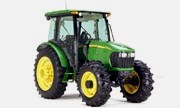 JD 5525
 JD 5083EN
 JD 5100GN
 JD 5125R
 210C Backhoe
 300D Backhoe
 310G Backhoe
 410G Backhoe
 710G Backhoe
 80 Loader
 100 Loader
 146 Loader
 148 Loader
 158 Loader
 168 Loader
 175 Loader
 522 Loader
 542 Loader
 540R Loader
 562 Loader
 563 Loader
 673 Loader
 741 Loader
 L108 Automatic
 L120 Automatic
 LA110 Automatic
 LA120 Automatic
 LA150 Automatic
 LT155
LT155 LT160 Automatic
 LT180 Automatic
 LTR180
 X165
X165 E100
E100 E120
E120 E150
E150 LTR166
 LA135
LA135 LA165
LA165 LX277
LX277 LX288
LX288 LX255
LX255 S240
S240 GT235
GT235 G110 Automatic
 JD 3203
 JD 5520
 JD 316
 JD 420
 JD 425
 JD 445
 JD_5050D
 X300
X300 X304
X304 X310
X310 X110 Automatic
 H310 Loader
 H340 Loader
 H360 Loader
 H380 Loader
 H480 Loader
 240 Loader
 245 Loader
 260 Loader
 265 Loader
 600R Loader
 620R Loader
 640R Loader
 660R Loader
 680R Loader
 JD_5039D
 X146R
X146R X360
X360 X155R
X155R X140 Automatic
 X350
X350 X380
X380 X500
X500 X590
X590 X700
X700 3036E
3036E 2038R
2038R 3038R
3038R 4049M
4049M JD 4100
 X738
X738 X740
X740 X748
X748 X749
X749 X950R
X950R JD 4510
 5045D
5045D 5050E
5050E 5060E
5060E 5078E
5078E