
________________________________________________________________________________
Borg and Beck Independent Clutch
Case IH Tractor 385/485/585/685 Borg
and Beck Independent Clutch Assembly
Before removing clutch, mark pressure plate to flywheel position for
reassembly. Install retainers made from stiff wire over PTO clutch
release levers to retain pressure of clutch springs. Remove bolts
securing clutch assembly to flywheel, then remove clutch being careful
not to drop inner clutch disc.
Install nine special long studs into appropriate holes in 912917 base
plate. Place three Code 3 spacers on base plate, then install clutch
assembly onto base plate and studs and arrange spacers so they are
located below pto release lever lugs of pressure plate.
Install flat washers and nuts on studs and tighten nuts evenly until
clutch is seated on base plate.
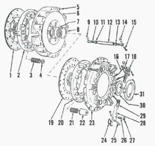
Fig.19. Case IH Tractor Borg and Beck Independent clutch used on
models with Independent pto
Mark positions of the following components so they can be reinstalled In
their original positions If reused: Pressure plates (2 and 20) and
covers (6 and 23), pressure plate lugs and re-tease levers (28) and
outer cover and release levers (18).
Install release lever actuator into base plate, depress pto release
levers and remove release lever retainer wires installed during removal.
Remove actuator from base plate. Remove release lever pivot pins and
remove levers from cover.
Remove six bolts retaining clutch cover (23) to separator housing (6).
Unscrew stud nuts evenly to relieve spring tension, then separate clutch
components.
Inspect all parts for excessive wear or other damage. Friction surfaces
of clutch cover and separator housing should be smooth and free of
cracks.
Surfaces may be reground providing amount of material removed does not
exceed 0.38 mm (0.015 inch). Check separator housing bearing (7) for
smooth operation and renew if necessary.
Renew pressure springs if rusted, distorted or weak. Renew insulating
washers (4) if damaged. Loose washers should be held in place in housing
with suitable adhesive.
Inspect release levers and pivot pins for wear or damage and renew as
needed. Renew release lever plates (30 and 31) if excessively worn.
To reassemble, install Case Tractor PTO pressure plate (2) on base plate
and position three Code 3 spacers under plate at release lever lugs.
Assemble PTO springs and separator housing on pressure plate.
Place three Code 13 spacers on friction surface of separator housing,
then install transmission pressure plate (20), aligning assembly marks
and positioning spacers under release lever lugs. Assemble springs and
outer cover on pressure plate.
Install flat washers and nuts on studs and tighten until clutch is
bottomed on base plate. Install six bolts retaining cover to separator
housing. Install release levers and lever plates.
Install short adapter and release lever actuator into base plate.
Actuate release levers about a dozen times to ensure components are
properly seated, then remove actuator.
Thread guide pin into adapter, then place Code 16X spacer on guide pin
with recessed side towards adapter. Install short gage on guide pin,
then adjust screws (26) on transmission clutch release levers until
lever plate just touches gage all the way around. Tighten locknuts to
secure adjustment.
Remove short adapter from base plate and install long adapter. Install
release lever actuator and depress pto release levers about a dozen
times to ensure parts are
properly seated. Remove actuator and install guide pin in adapter.
Install Code 16X spacer with recessed side facing down. Install long
adjusting gage on guide, then adjust PTO release levers (18) until lever
plate just touches gage all
the way around. Remove gage, spacer and guide pin.
Remove pto release lever plate and PTO release lever pivot pins. Swing
release levers outward clear of clutch. Install three stiff wire
retainers over transmission release
levers to retain clutch spring tension.
Remove cover retaining bolts, then loosen stud nuts evenly and lift
clutch cover from separator housing. Remove spacers and install
transmission clutch disc on
separator housing with side marked "Flywheel" towards housing. Reinstall
cover assembly.
Use a pilot tool or a clutch drive shaft to align clutch disc with
separator housing bearing, then install nuts and washers on three studs
and tighten evenly to clamp cover
to base plate. Install the six cover retaining bolts. Remove wire
retainers from transmission clutch levers.
Reinstall Case Tractor 385/485/585/685 pto clutch release levers, pivot
pins and lever plate. Secure pto levers with stiff wire retainers used
during removal, then loosen
the three stud nuts and lift clutch assembly from base plate.
To reinstall, install inner disc with longer hub side towards flywheel.
Position clutch assembly in flywheel aligning match marks made during
removal. Use a suitable pilot
shaft to align clutch discs, then tighten clutch mounting bolts evenly.
Remove pilot tool from clutch.
________________________________________________________________________________
________________________________________________________________________________________
 CASE IH SPECS
 J.I. CASE SPECS
 PROBLEMS
 LOADERS
________________________________________________________________________________________
| CASE IH TRACTORS SPECIFICATIONS |
 FARMALL 110A
 FARMALL 120A
 FARMALL 30C
 FARMALL 75C
 MAGNUM 280
________________________________________________________________________________________
 580E Backhoe
 580L Backhoe
 580N Backhoe
 580 Super L
 580SM Backhoe
________________________________________________________________________________________
________________________________________________________________________________________
 580SLE Backhoe
 580SN Backhoe
 580M Backhoe
 580 Super E
 580ST Backhoe
________________________________________________________________________________________
 MAGNUM 310
 MAGNUM 340
 MAXXUM 110CVX
 MAXXUM 120CVX
 MAXXUM 125
________________________________________________________________________________________
 1394
1394 1455XL
 1494
1494 1594
1594 3230
3230________________________________________________________________________________________
 4210
4210 585XL
585XL 633
633 695XL
695XL 733
733________________________________________________________________________________________
 MX110
MX110 MX135
MX135 MX150
MX150 MXU110
 MXU135
________________________________________________________________________________________
 PUMA 175CVX
 PUMA 185CVX
 PUMA 200CVX
 PUMA 240CVX
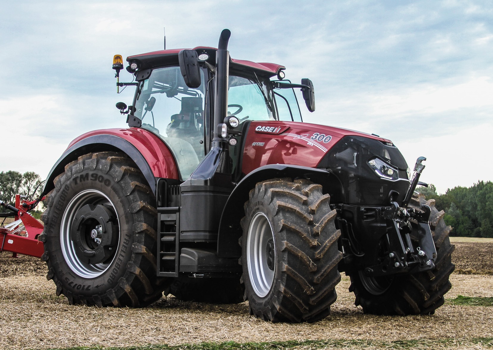 OPTUM 300
________________________________________________________________________________________
 FARMALL 50B
 FARMALL 95U
 FARMALL 125A
 PUMA 150
 PUMA 165
________________________________________________________________________________________
 MAGNUM 210
 MX 170
 MAXXUM 150
 OPTUM 270
 MAGNUM 315
________________________________________________________________________________________
 FARMALL 70
 FARMALL 75N
 FARMALL 95C
 FARMALL 105N
 FARMALL 30B
________________________________________________________________________________________
| CASE IH FRONT END LOADERS SPECS |
 L103 Loader
 L104 Loader
 L105 Loader
 L106 Loader
 L107 Loader
________________________________________________________________________________________
 L108 Loader
 L130 Loader
 L160 Loader
 L300 Loader
 L340 Loader
________________________________________________________________________________________
 L350 Loader
 L360 Loader
 L530 Loader
 L540 Loader
 L545 Loader
________________________________________________________________________________________
 L550 Loader
 L555 Loader
 L560 Loader
 L565 Loader
 L570 Loader
________________________________________________________________________________________
 L575 Loader
 L720 Loader
 L730 Loader
 L735 Loader
 L740 Loader
________________________________________________________________________________________
 LRZ 95
 LRZ 100
 LRZ 120
 LRZ 130
 LRZ 150
________________________________________________________________________________________
 L745 Loader
 L750 Loader
 L755 Loader
 L760 Loader
 L765 Loader
________________________________________________________________________________________
 L770 Loader
 L775 Loader
 L780 Loader
 L785 Loader
 L795 Loader
________________________________________________________________________________________
 90 Loader
 890 Loader
 2200 Loader
 2250 Loader
 LX156 Loader
________________________________________________________________________________________