
________________________________________________________________________________
Hydraulic Pump of Case IH 385, 585 Tractor Steering System
Case 385, 585 Tractors may be equipped with either Sun-strand or Plessy
hydraulic gear type pumps. The maximum pump output is controlled by
engine rpm and the number of teeth on the pump drive gear.
The priority flow divider sends approximately 3 gpm to the steering
system and the balance is used for the draft and position controls on
the hitch lift system and for the auxiliary control valves.
Overhaul
To remove the hydraulic pump, first drain all compartments of Hy-Tran
Plus fluid. Although the pump can be removed with left rear wheel
Installed, most mechanics prefer to remove left rear wheel to provide
more room to remove the multiple control valve and pump assembly.
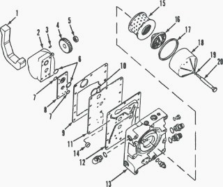
Fig.9
Thoroughly clean the area around the multiple control valve, then remove
the hydraulic filter assembly (15 through 20—Fig, 9).
Disconnect steering lines, oil cooler line, hitch supply line, auxiliary
valves return line and pto line from multiple control valve (13).
Immediately cap or plug all openings. On models equipped with XL cab,
remove left console.
On Case IH 585, 385 Tractor, disconnect and remove park brake warning
switch wires and linkage. Disconnect and remove pto operating lever.
Remove two cap screws from opposite sides of multiple control valve.
Install two 3/8 x 5 inch guide studs in the holes to aid in removal and
installation of the assembly. Remove the balance of the retaining cap
screws, then slide multiple control valve outward from rear main frame.
Lay the assembly on a clean bench. Remove the four cap screws and copper
washers, then lift off hydraulic pump assembly (2) and spacer plate (8),
if so equipped.
Spacer plate (8) is used only on Case 385, 585 Tractor equipped with a
23 tooth pump drive gear.
Disassembly of the pump is obvious after examination of the unit. Remove
nut (5), drive gear (4) and Woodruff key (3). Remove end plate cap
screws and separate pump components.
Clean and inspect all parts. If any parts show excessive wear or other
damage, renew pump assembly. A seal kit is available for resealing the
pump.
When reassembling pump, tighten end plate cap screws to a torque of
20-23 ft .-lbs. (27-31 N-m). Install Woodruff key (3), place drive gear
(4) on shaft and install and tighten nut (5) to a torque of 45-50
ft.-lbs. (61-68 Nm).
Hold drive gear in a vise while tightening nut. Check condition of foam
seal (1). If damaged or loose, remove and discard seal. Clean seal area
with a rag and adhesive solvent, then dry the housing.
Apply a thin coat of oil resistant adhesive to the housing and to a new
foam seal. Let adhesive dry one to two minutes, then install foam seal
on pump housing. Allow adhesive to dry at least another 30 minutes
before installing pump assembly.
When reassembling, use all new "O" rings, seal ring and gaskets. Install
pump and spacer (8), if so equipped, to multiple control valve. Use new
copper washers on the four pump retaining cap screws. Install and
tighten cap screws to a torque of 18-24 ft.-lbs. (24-28 N-m).
Lubricate foam seal (1) with Hy-Tran Plus fluid and reinstall multiple
control valve and pump assembly by reversing the removal procedure.
Tighten multiple control valve retaining cap screws to a torque of 33-37
ft.-lbs. (45-50 N-m).
Reinstall hand park brake linkage and pto linkage. Then, using a new
filter element (15), "o" rings and gasket, install hydraulic filter
assembly. Tighten filter center bolt to a torque of 12-16 ft.-lbs.
(16-21 N-m).
Connect all disconnected hydraulic lines. Fill transmission to correct
level on dipstick with Hy-Tran Plus oil. Refill capacity is 36 U.S.
quarts (34.0 L) on tractors without front drive axle and 38.6 U.S.
quarts (36.5 L) on tractors with front drive axle.
Case IH 385, 585 Tractor Hydraulic
pump test
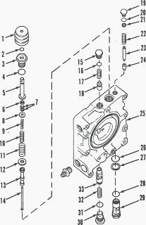
Fig.10
To check flow and pressure of the hydraulic pump, first remove the plug
(Fig. 10) for the flow divider. Remove spring (32) and spool (33), then
reinstall plug. Remove the pilot relief valve (29) and install a test
pilot relief valve.
Disconnect the power steering supply pipe (directly below hydraulic
filter). Cap the pipe and union on multiple control valve with high
pressure caps. Disconnect hitch supply line (bottom rear line on
multiple control valve) and cap the line.
Connect the inlet hose from the flowmeter to the hitch supply union on
the multiple control valve. Place outlet hose from flowmeter into
transmission oil fill hole and wire in place. Fully open load valve on
flowmeter.
Start Case 385, 585 Tractor engine and operate at a speed of 2180 rpm.
Record the flow. Close load control valve to obtain a reading of 2000
psi (13790 kPa) on pressure gage, then record the flow.
Fully open the load valve and stop engine. The second flow reading must
not be less than 90 percent of the first flow reading. If second reading
is too low, check for the following conditions: Low oil level, Clogged
filter, Faulty pump.
Remove test pilot relief valve and using new seal rings, install
original pilot relief valve. Remove flow divider plug (30) and install
spool (33) and spring (32). Reinstall and tighten plug.
Remove caps from steering supply line and union, then connect steering
line. Disconnect and remove flowmeter and connect hitch supply line.
Start tractor and bleed air from steering system.
________________________________________________________________________________
________________________________________________________________________________________
 CASE IH SPECS
 J.I. CASE SPECS
 PROBLEMS
 LOADERS
________________________________________________________________________________________
| CASE IH TRACTORS SPECIFICATIONS |
 FARMALL 110A
 FARMALL 120A
 FARMALL 30C
 FARMALL 75C
 MAGNUM 280
________________________________________________________________________________________
 580E Backhoe
 580L Backhoe
 580N Backhoe
 580 Super L
 580SM Backhoe
________________________________________________________________________________________
________________________________________________________________________________________
 580SLE Backhoe
 580SN Backhoe
 580M Backhoe
 580 Super E
 580ST Backhoe
________________________________________________________________________________________
 MAGNUM 310
 MAGNUM 340
 MAXXUM 110CVX
 MAXXUM 120CVX
 MAXXUM 125
________________________________________________________________________________________
 1394
1394 1455XL
 1494
1494 1594
1594 3230
3230________________________________________________________________________________________
 4210
4210 585XL
585XL 633
633 695XL
695XL 733
733________________________________________________________________________________________
 MX110
MX110 MX135
MX135 MX150
MX150 MXU110
 MXU135
________________________________________________________________________________________
 PUMA 175CVX
 PUMA 185CVX
 PUMA 200CVX
 PUMA 240CVX
 OPTUM 300
________________________________________________________________________________________
 FARMALL 50B
 FARMALL 95U
 FARMALL 125A
 PUMA 150
 PUMA 165
________________________________________________________________________________________
 MAGNUM 210
 MX 170
 MAXXUM 150
 OPTUM 270
 MAGNUM 315
________________________________________________________________________________________
 FARMALL 70
 FARMALL 75N
 FARMALL 95C
 FARMALL 105N
 FARMALL 30B
________________________________________________________________________________________
| CASE IH FRONT END LOADERS SPECS |
 L103 Loader
 L104 Loader
 L105 Loader
 L106 Loader
 L107 Loader
________________________________________________________________________________________
 L108 Loader
 L130 Loader
 L160 Loader
 L300 Loader
 L340 Loader
________________________________________________________________________________________
 L350 Loader
 L360 Loader
 L530 Loader
 L540 Loader
 L545 Loader
________________________________________________________________________________________
 L550 Loader
 L555 Loader
 L560 Loader
 L565 Loader
 L570 Loader
________________________________________________________________________________________
 L575 Loader
 L720 Loader
 L730 Loader
 L735 Loader
 L740 Loader
________________________________________________________________________________________
 LRZ 95
 LRZ 100
 LRZ 120
 LRZ 130
 LRZ 150
________________________________________________________________________________________
 L745 Loader
 L750 Loader
 L755 Loader
 L760 Loader
 L765 Loader
________________________________________________________________________________________
 L770 Loader
 L775 Loader
 L780 Loader
 L785 Loader
 L795 Loader
________________________________________________________________________________________
 90 Loader
 890 Loader
 2200 Loader
 2250 Loader
 LX156 Loader
________________________________________________________________________________________