________________________________________________________________________________
Case 1390, 1690 Tractor Power Shift Transmission – control valve
Power shift Case 1690, 1194, 1290, 1390, 1190 Tractor transmission
consists of a three forward, one reverse mechanical gear section coupled
with a four-speed, hydraulic power shift section providing twelve
forward and four reverse speed selections.
Front four-speed planetary section is hydraulically controlled and
changes between any of the ratios can be made while tractor is in motion
without use of transmission clutch. Gear (range) speeds are selected
manually and trans-mission clutch must be used.
Power shift control valve
![]()
Fig.32. Identify power shift front sequence valve (2) and rear
sequence valve (3) prior to removal as valve are not Interchangeable
Flow restrictors are located in front end rear planetary brake pressure
lines (4 and 5).
Power shift control valve spool and body (8) are serviced as an assembly
only. However, relief valve spring (2) and spool (3) are available
separately.
To remove control valve, first remove platform or cab, if so equipped.
Remove fuel tanks. Disconnect wiring harness to rear of tractor and
disconnect neutral start switch wires. Remove range and power shift
selector assemblies from transmission cover.
Disconnect hydraulic lines and control linkage from remote valve. Remove
mounting bolts and remove remote valve assembly. Remove transmission
cover mounting bolts and remove wedge and shim from front of cover. Use
a hoist to lift transmission cover from main frame.
Disconnect hydraulic lines from control valve (1). Mark sequence valves
(2 and 3) so they can be reinstalled in their original positions, then
remove both valves. Remove control valve mounting bolts and remove valve
assembly.
![]()
Fig.33. Power shift control valve, sequence valves and related
oil lines
1.Adjusting screw, 2.Spring, 3.Relief valve plunger, 4.Plug,
5.Restrictor plate, 6.Oil supply pipe, 7.Detent spring & ball, 8.Control
valve body & spool, 9.Restrictors, 10.Lubrication tube, 11.Sealing
washer, 12.Sequence valve front, 13."O" ring, 14.Sequence valve rear,
15.Power shift hydraulic pump, 16.Planetary brake cylinder front,
17.Planetary brake cylinder rear
To disassemble valve for inspection, remove seal wire from relief valve
adjusting screw (1). Remove adjusting screw while noting number of turns
required to remove screw for use in reassembly.
Remove spring (2) and relief valve spool (3). Remove plug and detent
spring and ball (7). Remove snap ring from valve spool, then withdraw
spool from valve body. Remove test port plug (4) and restrictor plate
(5).
Inspect all parts for wear or scoring. Be sure control valve spool and
bore are free of scoring or other damage. Reassemble valve by reversing
disassembly procedure. Lubricate all parts during reassembly.
Setting control valve pressure
Reinstall control valve and tighten mounting bolts to 34 N-m (25
ft.-lbs.) torque. Install front and rear sequence valves. Move control
valve spool fully forward and remove plug (4) from control valve test
port.
Install Case IH 1390, 1690 Tractor transmission cover and remote valve
assembly. Do not install power shift selector lever at this time. Remove
test port plug from right side of transmission cover. Install special
adapter and a 0-1000 kPa (0-150 psi) pressure gage (1) through opening
in cover and into test port.
Use a remote fuel supply to operate tractor. Start engine and run to
bring transmission fluid temperature to approximately 45 °C (115°F).
Transmission housing must be warm to the touch. With engine running at
1500 rpm, pressure reading should be 350-560 kPa (77-81 psi) or 600-625
kPa (87-91 psi).
To adjust pressure, insert a screwdriver through power shift selector
opening in transmission cover and turn relief valve adjusting screw
clockwise to increase pressure or counterclockwise to reduce pressure.
Stop engine and remove manifold and gage. Remove remote valve and
transmission cover. Install plug in control valve test port and install
a lock wire in relief valve adjusting screw to secure adjustment.
Reassemble Case 1390, 1690 Tractor by reversing disassembly procedure
while noting the following special instructions. Tighten remote valve
mounting bolts to 47-57 N-m (35-40 ft.- lbs.) torque.
Tighten transmission cover % inch mounting bolts to 102-122 N-m (75-90
ft.-lbs.) torque and % inch mounting bolts to 165-200 N-m (120-130
ft.-lbs.) torque. Tighten range and power shift selector housing
mounting bolts to 23-28 N-m (17-20 ft.-lbs.) torque.
Sequence valves
The sequence valves (2 and 3) control release timing of front and rear
planetary clutch units. Front and rear sequence valves are mechanically
identical, however, they have different pressure settings.
Therefore, be sure valves are properly marked before removal so they can
be reinstalled in their original positions. Front sequence valve
controls release of front planetary clutch, while rear sequence valve
controls release of rear planetary clutch.
To remove sequence valves, it is first necessary to remove Case IH 1390,
1690 transmission cover. Sequence valves are serviced as a complete
assembly only, but valves may be disassembled for cleaning and
inspection. It is recommended adjustment screw setting not be disturbed
during disassembly.
All new sequence valves obtained through parts are adjusted at factory
to rear sequence valve pressure setting (which is lower than front
setting). If a new sequence valve is to be installed in front position,
increase factory setting by turning adjusting screw clockwise two full
turns.
![]()
Fig.34. Power shift sequence valve. Adjustment screw (11)
setting should not be changed unless valve pressure is to be reset
1.Pressure line, 2.Ganket, 3.Valves body, 4."O" ring, 5.Piston,
6.Spring, 7.Sprint neat, 8.Gasket, 9.End cap, 10.Locknut, 11.Adjusting
screw
Pressure setting of sequence valves can be checked and adjusted using a
suitable hand pressure pump and a 0-400 kPa (0-60 psi) pressure gage.
Remove hydraulic pressure line from valve, block orifice in piston with
tape and reinstall pressure pipe.
Connect sequence valve to hand pressure pump and pressure gage. Operate
hand pump slowly and note pressure reading at point pressure makes a
rapid drop indicating valve opened. Adjust screw (11) until pressure
release point is 210-220 kPa (32-33 psi).
If valve is to be installed in rear position, tighten jam nut to secure
adjusting screw at this setting. If valve is to be installed in front
position, turn screw clockwise an additional two turns and secure with
jam nut. Remove tape from piston orifice, reassemble valve and install
in proper position.
Power shift hydraulic pump
The power shift hydraulic pump is mounted on lower right-hand corner of
range gearbox front cover. The pump is gear driven from reverse gear of
range Case 1390, 1690 Tractor transmission.
To remove pump, first separate power shift transmission from main frame.
Remove manifold and pump mounting bolts, then remove pump assembly from
rear side of housing.
Use a suitable puller to remove pump drive gear. Remove Woodruff key,
then separate pump rotor assembly from pump body.
![]()
Fig.35. Power shift hydraulic pump
1."O" rings, 2.Bushings, 3.Idler gear, 4.Driven gear, 5.Bushing, 6."O"
rings, 7.Pump body, 8.Drive gear
Inspect all parts for wear or damage. Pump rotors and bearings are
serviced as a complete set. Renew all "O" rings.
When reassembling, make sure sides of bearings with oil grooves are
against gears. Lubricate all parts with clean oil during assembly.
Install drive gear using a new locknut and tighten nut to 73-86 N-m
(54-64 ft.-lbs.) torque.
Reinstall pump and manifold using new "O" rings in oil ports. Tighten
mounting bolts to 23-27 Nm (17-20 ft.-lbs.) torque.
________________________________________________________________________________
 CASE IH SPECS
 J.I. CASE SPECS
 PROBLEMS
 LOADERS
________________________________________________________________________________________
| CASE IH TRACTORS SPECIFICATIONS |
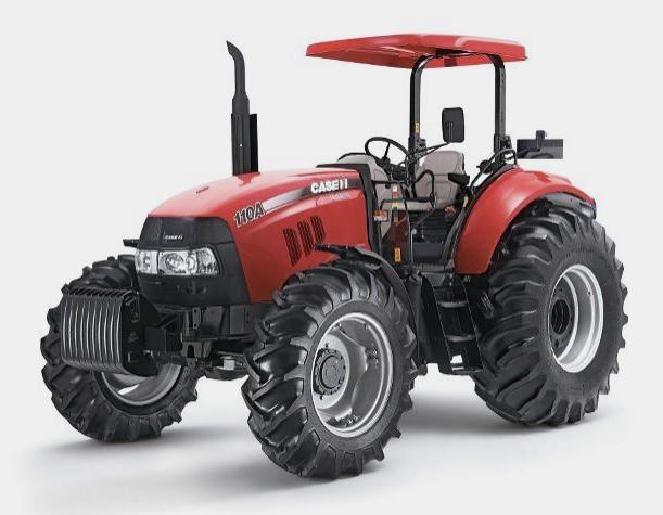 FARMALL 110A
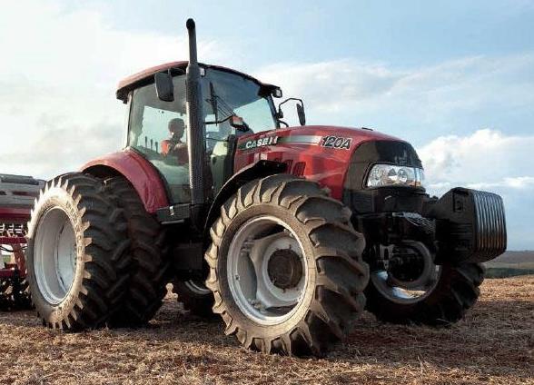 FARMALL 120A
 FARMALL 30C
 FARMALL 75C
 MAGNUM 280
________________________________________________________________________________________
 580E Backhoe
 580L Backhoe
 580N Backhoe
 580 Super L
 580SM Backhoe
________________________________________________________________________________________
 580SLE Backhoe
 580SN Backhoe
 580M Backhoe
 580 Super E
 580ST Backhoe
________________________________________________________________________________________
 MAGNUM 310
 MAGNUM 340
 MAXXUM 110CVX
 MAXXUM 120CVX
 MAXXUM 125
________________________________________________________________________________________
 1394
1394 1455XL
 1494
1494 1594
1594 3230
3230________________________________________________________________________________________
 4210
4210 585XL
585XL 633
633 695XL
695XL 733
733________________________________________________________________________________________
 MX110
MX110 MX135
MX135 MX150
MX150 MXU110
 MXU135
________________________________________________________________________________________
 PUMA 175CVX
 PUMA 185CVX
 PUMA 200CVX
 PUMA 240CVX
 OPTUM 300
________________________________________________________________________________________
 FARMALL 50B
 FARMALL 95U
 FARMALL 125A
 PUMA 150
 PUMA 165
________________________________________________________________________________________
 MAGNUM 210
 MX 170
 MAXXUM 150
 OPTUM 270
 MAGNUM 315
________________________________________________________________________________________
 FARMALL 70
 FARMALL 75N
 FARMALL 95C
 FARMALL 105N
 FARMALL 30B
________________________________________________________________________________________
| CASE IH FRONT END LOADERS SPECS |
 L103 Loader
 L104 Loader
 L105 Loader
 L106 Loader
 L107 Loader
________________________________________________________________________________________
 L108 Loader
 L130 Loader
 L160 Loader
 L300 Loader
 L340 Loader
________________________________________________________________________________________
 L350 Loader
 L360 Loader
 L530 Loader
 L540 Loader
 L545 Loader
________________________________________________________________________________________
 L550 Loader
 L555 Loader
 L560 Loader
 L565 Loader
 L570 Loader
________________________________________________________________________________________
 L575 Loader
 L720 Loader
 L730 Loader
 L735 Loader
 L740 Loader
________________________________________________________________________________________
 LRZ 95
 LRZ 100
 LRZ 120
 LRZ 130
 LRZ 150
________________________________________________________________________________________
 L745 Loader
 L750 Loader
 L755 Loader
 L760 Loader
 L765 Loader
________________________________________________________________________________________
 L770 Loader
 L775 Loader
 L780 Loader
 L785 Loader
 L795 Loader
________________________________________________________________________________________
 90 Loader
 890 Loader
 2200 Loader
 2250 Loader
 LX156 Loader
________________________________________________________________________________________