________________________________________________________________________________
Case 1490, 1294 Tractor Synchromesh transmission with end plates, shift rods and shift forks
Remove operations
Remove platform or cab if so equipped. Drain oil from Case 1294, 1394,
1490, 1494, 1594 Tractor transmission and final drive units. Raise rear
of tractor and install suitable support stands under center of rear main
frame and at each side of front frame rails.
Disconnect battery ground cable and rear wiring harness connector. On
left-hand side, remove brake cables from hand lever, remove knobs from
dump valve lever (if so equipped) and three-way valve lever and remove
axle cover mounting bolts.
On right-hand side, disconnect hydraulic control lever assembly and
remove axle cover mounting bolts. Unbolt and remove fenders, axle cover
and seat as one unit.
Disconnect and remove drawbar assembly and hitch lift arms, leveling
levers and lower links. Remove external hydraulic filter. Disconnect
hydraulic hoses and lines from remote valve, then remove remote valve
and couplers.
Disconnect cable from draft sensing unit. Use a hoist to support pto
assembly. Remove pto housing mounting bolts and install two guide studs.
Remove pto unit and withdraw pto drive shaft.
Disconnect brake lines and cap openings. Push differential lock pedal
down and secure with wire to hold it in engaged position. Support final
drive with suitable hoist and lifting bracket, remove mounting bolts and
remove final drive assembly.
Repeat for opposite side. Push differential lock sleeve in and down to
disengage from selector fork, then remove sleeve and spring.
Release differential lock pedal. Pull sleeve and spring away from
differential and put a piece of fiat metal between spring and
differential to hold spring clear while removing axle housing.
Support axle housing with a hoist and sling, remove mounting bolts and
remove axle housing from main frame.
Remove gear selector assemblies from transmission cover. Remove cover
mounting bolts and lift out wedge and shims from front of transmission
cover. Lift cover from rear main frame.
Attach a lifting eye to transmission rear end frame, then use a hoist to
support transmission unit. Remove snap ring from groove in clutch shaft
and slide coupling forward.
On Case 1490, 1294 Tractor equipped with David Brown front drive axle,
remove bolt from drive shaft coupler and move coupler rearward.
On all models, remove transmission mounting bolts and bushings. Move
transmission rearward to disengage drive couplers, then lift
transmission unit from frame. Retain any shims used with clutch shaft
coupler.
Reinstall Operations
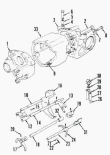
Fig.15. View of end plates, shift rods and shift forks
1.Front end plate, 2.Top spacer bar, 3.Rear end plate, 4.Shim,
5.Bushing, 6.Mounting bolts, 7.Tab washer, 8.Differential cap bolt,
9.Bottom spacer bar, 10.2nd & 3rd shift rod, 11.2nd & 3rd selector,
12.1st & reverse selector, 13.1st & reverse shift fork, 14.1st & reverse
shift rod, 15.Gear lock, 16.2nd & 3rd shift fork, 17.Shift fork,
slow/normal, 18.Slow/normal shift rod, 19.Selector, 20.Roll pin,
21.Detent ball, 22.Detent spring, 23.Range shift rod, 24.Shifter fork,
Hi-Lo, 25.Sleeve, 26.Steel ball, 27.Plunger, 28.Plunger, 29.Shim,
30.Safety start switch, 31.Hi - Lo selector jaw, 32.Sleeve, 33.Spacer
Clean all foreign material from housing mounting surfaces. Install front
drive axle coupler (if so equipped) on pinion shaft. Install original
shims onto transmission input shaft and position coupler on clutch
shaft.
Install Case IH 1294, 1490 Tractor transmission into main frame and
slide it forward into couplers. Install transmission mounting bolts
without the bushings (5).
Be sure both lugs of transmission front housing contact the frame. If
lugs are not flat on frame, loosen the four transmission housing nuts
and push housing down against frame. Tighten nuts to 95 Nm (70 ft.-lbs.)
torque when lugs are flat on frame.
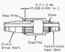
Fig.16. Clearance between transmission clutch shaft coupler and
snap ring should be 0.2-1.0 mm (0.008-0.040 Inch). Add or subtract shims
to adjust
Remove transmission mounting bolts, reinstall bolts with bushings and
tighten to 163 Nm (120 ft.-lbs.) torque. Use a feeler gage to check
clearance between bolt heads and housing lugs. Clearance should be
0.08-0.50 mm (0.003-0.020 inch). If necessary, install shims (4) below
bushings (5) to obtain desired clearance.
Measure clearance between clutch shaft coupler and snap ring. Clearance
should be 0.2-1.0 mm (0.008-0.040 inch). Add or remove shims on
transmission input gear to obtain correct clearance.
On Case 1490, 1294 Tractor equipped with David Brown front drive axle,
install bolt and locknut in transfer gearbox coupler.
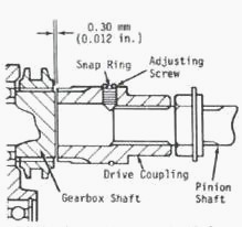
Fig.17. On tractor equipped with Carraro front drive axle,
clearance between transfer gearbox shaft and pinion shaft coupler must
not exceed 0.30 mm (0.012 Inch)
On Case IH 1294, 1490 Tractor equipped with Carraro front drive axle,
measure clearance between transfer gearbox shaft and pinion shaft
coupler. If clearance exceeds 0.30 mm (0.012 inch), unseat snap ring
that holds coupler adjusting screw.
Turn adjusting screw to move coupler until desired clearance is
obtained, then reinstall snap ring
over adjusting screw. Install transmission cover, wedge and shims, but
do not tighten mounting bolts.
Position differential lock sleeve in right-hand side of rear axle
housing. Groove in sleeve must be aligned with differential lock
selector fork.
Install rear axle housing onto Case 1490, 1494 transmission housing
making certain that lubrication supply tube in axle housing is connected
with transmission lubrication tube. Be sure small diameter lubrication
tube in rear axle housing is installed into hole in lubrication flange
for pto shaft.
Install differential lock return spring into axle housing through
right-hand axle hole. Use special tool, or other suitable tool, to
insert differential lock sleeve into axle housing.
Push sleeve in and down to engage selector fork with groove in sleeve.
Push sleeve in until it engages internal splines of differential
carrier, then wire differential lock linkage in engaged position.
Install differential lock spring into differential and differential lock
sleeve.
Insert special tool, or other suitable tool, into axle housing and
engage tool with splines of lock sleeve. Be sure groove in sleeve is
engaged with selector fork, then lift sleeve and turn tit engage sleeve
with differential lock ring gear. Use wire to fasten differential lock
linkage in engaged position.
Tighten 0,5 inch axle housing mounting torque bolts to 110-130 Nm (80-95
ft.-lbs.) torque and mounting bolts to 205-245 N-m (150-180 ft.-lbs.)
torque. Tighten transmission cover mounting bolts to 110-130 N-m (80-95
ft.-lbs.) torque.
Install final drive assemblies, pto drive shaft and pto assembly. Pto
unit should slide easily into position. Do not use mounting bolts to
pull pto into position as damage to engine crankshaft thrust surfaces
could result. Complete installation by reversing the removal procedure.
________________________________________________________________________________
________________________________________________________________________________________
| CASE IH TRACTORS SPECIFICATIONS |
________________________________________________________________________________________
________________________________________________________________________________________
________________________________________________________________________________________
________________________________________________________________________________________
________________________________________________________________________________________
________________________________________________________________________________________
________________________________________________________________________________________
________________________________________________________________________________________
________________________________________________________________________________________
________________________________________________________________________________________
________________________________________________________________________________________
| CASE IH FRONT END LOADERS SPECS |
________________________________________________________________________________________
________________________________________________________________________________________
________________________________________________________________________________________
________________________________________________________________________________________
________________________________________________________________________________________
________________________________________________________________________________________
________________________________________________________________________________________
________________________________________________________________________________________
________________________________________________________________________________________
 CASE IH SPECS
 J.I. CASE SPECS
 PROBLEMS
 LOADERS
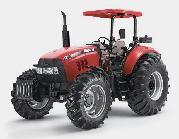 FARMALL 110A
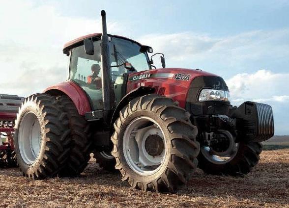 FARMALL 120A
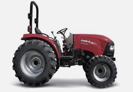 FARMALL 30C
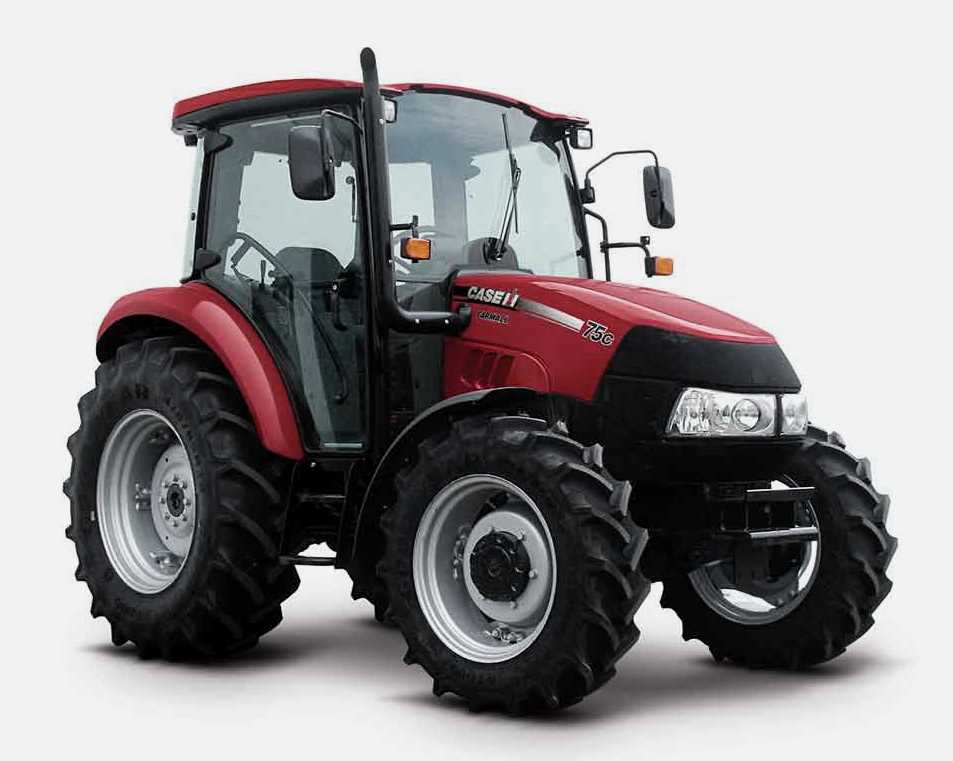 FARMALL 75C
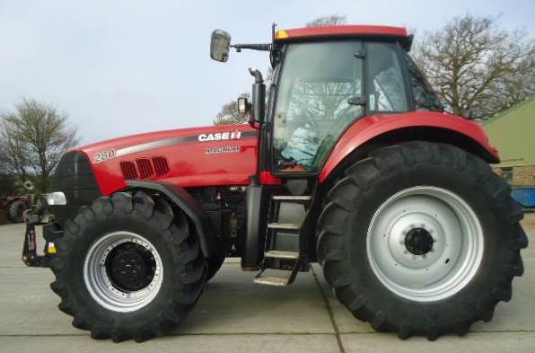 MAGNUM 280
 580E Backhoe
 580L Backhoe
 580N Backhoe
 580 Super L
 580SM Backhoe
 580SLE Backhoe
 580SN Backhoe
 580M Backhoe
 580 Super E
 580ST Backhoe
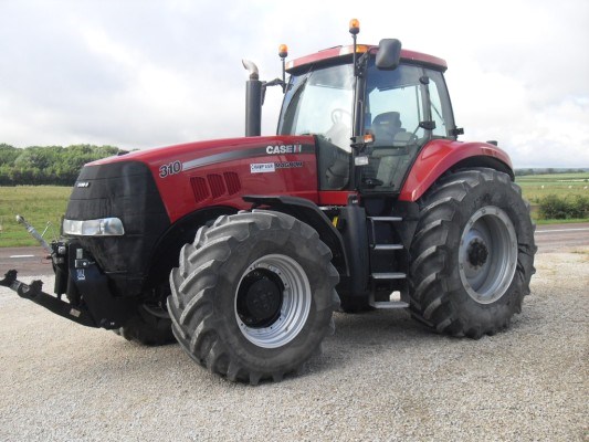 MAGNUM 310
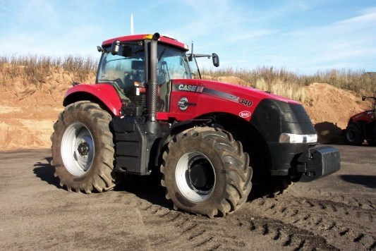 MAGNUM 340
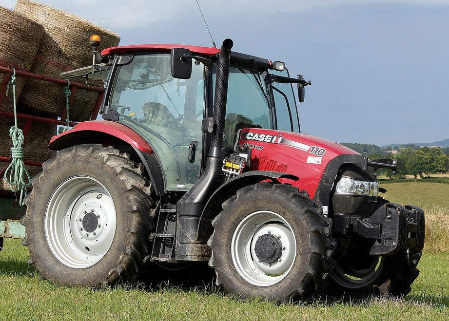 MAXXUM 110CVX
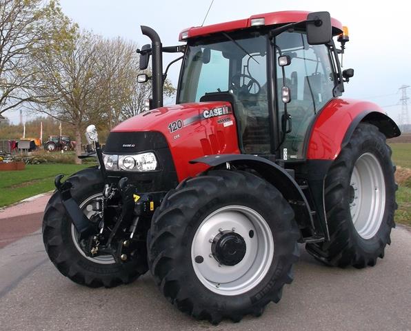 MAXXUM 120CVX
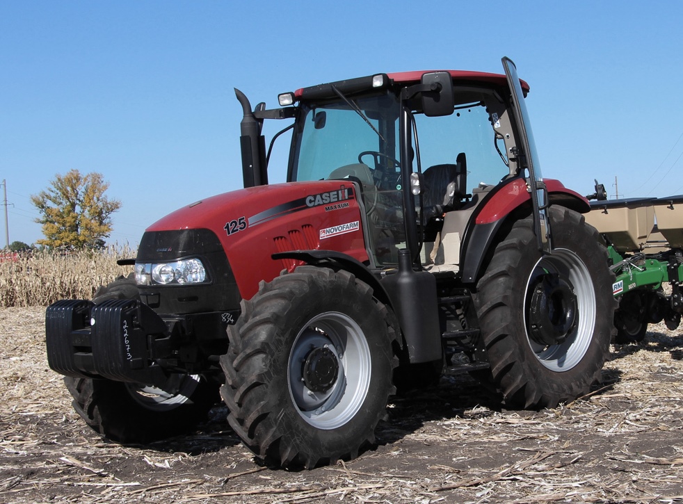 MAXXUM 125
 1394
1394 1455XL
 1494
1494 1594
1594 3230
3230 4210
4210 585XL
585XL 633
633 695XL
695XL 733
733 MX110
MX110 MX135
MX135 MX150
MX150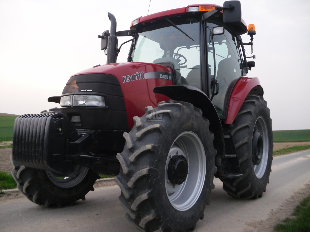 MXU110
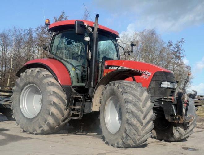 MXU135
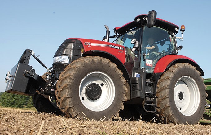 PUMA 175CVX
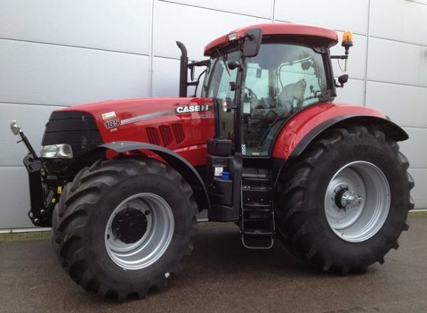 PUMA 185CVX
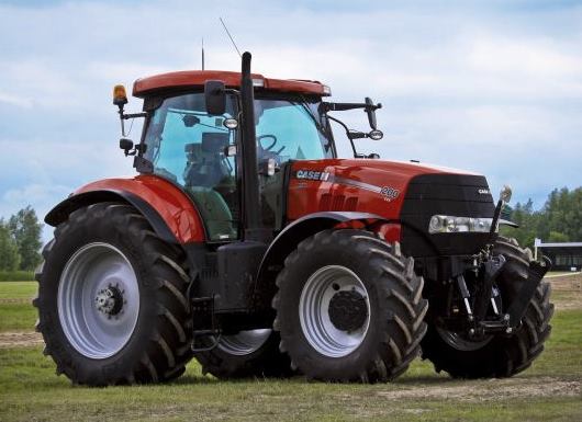 PUMA 200CVX
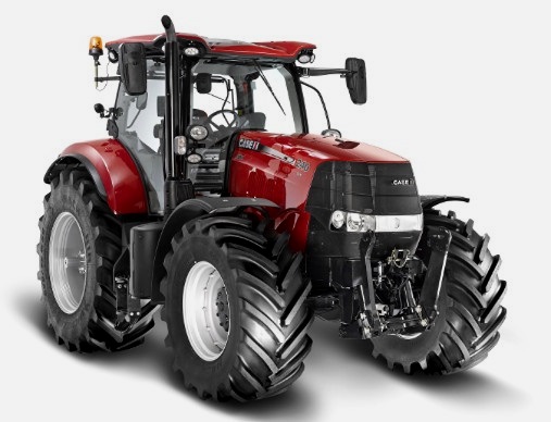 PUMA 240CVX
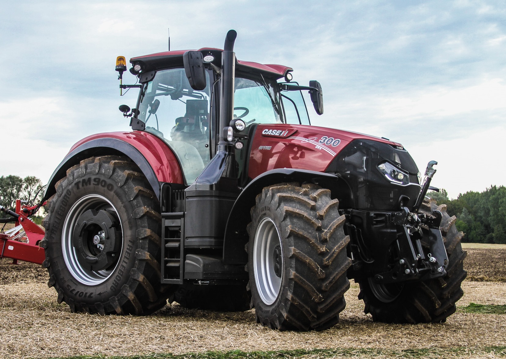 OPTUM 300
 FARMALL 50B
 FARMALL 95U
 FARMALL 125A
 PUMA 150
 PUMA 165
 MAGNUM 210
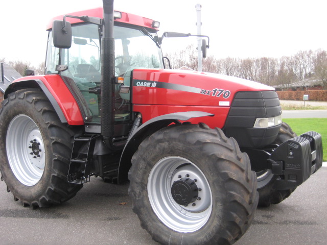 MX 170
 MAXXUM 150
 OPTUM 270
 MAGNUM 315
 FARMALL 70
 FARMALL 75N
 FARMALL 95C
 FARMALL 105N
 FARMALL 30B
 L103 Loader
 L104 Loader
 L105 Loader
 L106 Loader
 L107 Loader
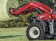 L108 Loader
 L130 Loader
 L160 Loader
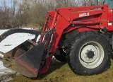 L300 Loader
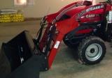 L340 Loader
 L350 Loader
 L360 Loader
 L530 Loader
 L540 Loader
 L545 Loader
 L550 Loader
 L555 Loader
 L560 Loader
 L565 Loader
 L570 Loader
 L575 Loader
 L720 Loader
 L730 Loader
 L735 Loader
 L740 Loader
 LRZ 95
 LRZ 100
 LRZ 120
 LRZ 130
 LRZ 150
 L745 Loader
 L750 Loader
 L755 Loader
 L760 Loader
 L765 Loader
 L770 Loader
 L775 Loader
 L780 Loader
 L785 Loader
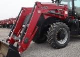 L795 Loader
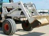 90 Loader
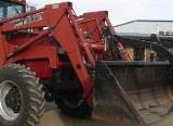 890 Loader
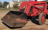 2200 Loader
 2250 Loader
 LX156 Loader