
________________________________________________________________________________
Case 1394, 1494 Tractor Synchromesh transmission with shift selector levers
Case IH 1294, 1394, 1490, 1494, 1594 Tractor synchromesh transmission
have a three forward and one reverse gear section and a four-speed range
section providing twelve forward and four reverse gear choices.
A synchromesh hub between second and third gear permits on the move gear
shifts from first to second and second to third and a down shift on the
move from third to second by depressing foot clutch and shifting.
Shift levers
![]()
Fig.8. View of range and transmission shift selector levers for
tractors without cabs equipped with synchromesh transmission
1.Knob, 2.Retaining ring, 3.Lever, 4.Boot, 5.Housing, 6.Ball housing,
7.Ball housing, 8.Roll pin, 9.Selector shaft arm, 10.Oil seal,
11.Selector shaft, 12.Selector lever, 13.Gasket, 14.Core plug, 15.Roll
pin, 16.Knob, 17.Retainer ring, 18.Lever, 19.Lever, 20.Housing,
21.Bushing, 22.Gasket, 23.Snap ring, 24.Bushing, 25.Roll pin,
26.Selector lever, 27.Selector lever, 28.Washer, 29.Selector tube,
30.Selector shaft, 31.Roll pin
Transmission or range selector lever assemblies may be removed as
separate units from transmission top cover. Shift rods are carried in
transmission assembly end plates.
Remove Case IH 1394, 1494 tractor
transmission
Remove muffler, air intake precleaner, engine hood and side covers.
Remove hand and foot operated throttle control rods and engine stop
cable.
Disconnect fuel lines, necessary power steering lines, tachometer drive
cable and all necessary electrical connections, then remove fuel tank
(without cab) and instrument panel.
Drain oil from transmission. Remove remote valve couplers and support
bracket. Disconnect remote valve hoses and remove remote valve assembly.
Disconnect draft sensing cable at hitch upper link connection. Remove
drawbar mounting bolts and lower drawbar assembly to the ground. Remove
vacuum switch from bottom of pto housing.
Attach a hoist to pto housing. Remove housing bolts and install a guide
stud on each side of housing. Slide housing rearward on studs and remove
pto unit from tractor. Withdraw pto clutch shaft from rear of tractor.
Remove hydraulic pump, pressure line retaining bracket and pump support
plate from rear of tractor.
Support each side of Case 1394, 1494 tractor with suitable stands. Raise
rear of tractor and position a suitable support stand under center of
rear frame.
Remove left and right wheels and final drive assemblies. Remove
right-hand brake assembly, right-hand seal, differential lock sleeve and
spring.
Remove transmission dipstick and transmission range and gear selector
lever assemblies from transmission cover. Remove mounting bolts from
transmission cover and rear axle case. Remove wedge and shim from front
of transmission cover. Lift transmission cover from housing.
Support axle housing with a hoist. Disconnect differential lock linkage
and hand brake linkage. Remove axle housing mounting bolts, then remove
housing from main frame.
Remove lubrication line from transmission. Remove mounting bolts from
clutch shaft bearing carrier. Remove transmission mounting bolts and
bushings. Remove transmission rearward from main frame.
Reinstall Case IH 1394, 1494 tractor
transmission
Using a hoist, install transmission assembly in main frame. Install
mounting bolts and bushings. Tighten bolts to 163 N-m (120 ft.-lbs,)
torque, then measure clearance between bolt heads and end plate using a
feeler gage.
Clearance should be 0.08-0.50 mm (0.003-0.020 inch). If clearance is not
within this range, add or remove shims (4) below bushing (5). Tighten
clutch shaft bearing retainer mounting bolts to 23-27 Nm (17-20
ft-Ibs.).
Apply gasket sealer to front mating surface of rear axle housing, then
install axle housing assembly. Tighten inch mounting bolts to 110-130
N-m (80-95 ft.-lbs.) torque and % inch mounting bolts to 205-245 N-m
(150-180 ft.-lbs.) torque. Connect differential lock linkage.
Apply gasket sealer to upper surface of rear axle housing. Install
transmission lubrication tube. Install IH Case 1394, 1494 transmission
cover and drive the wedge and shim into gap at front of cover.
Tapered side of wedge must be against clutch housing. Tighten diameter
rear mounting bolts to 110-130 N-m (80-95 ft.-lbs.) torque and diameter
rear mounting bolts to 205-245 N-m (150-180 ft-lbs.) torque.
Tighten side and front mounting bolts to 110-130 N-m (80-95 ft.-lbs.)
torque. Install gear selector housings and tighten mounting bolts to
23-27 N-m (17-20 ft.-lbs.) torque.
Install spring for differential lock in right side axle opening and
install differential locking sleeve using special tool. Use wire to hold
differential lock linkage in engaged position until final drive is
installed. Install axle housing seals and brake shoes.
Install final drive assemblies and tighten mounting bolts to 68 N-m (50
ft.-lbs.) torque. Install wheels and tighten nuts to 190 N-m
(140ft.-lbs.) torque.
Remove support stands. Connect brake lines and parking brake linkage.
Install hydraulic pump support plate, pressure tube retainer bracket and
hydraulic pump.
Tighten pump mounting bolts to 47-57 N-m (35-40 ft.-lbs.) torque.
Install pto drive shaft. Using a hoist, install pto assembly. Put pto in
gear and turn output shaft to engage splines of drive shaft and teeth of
hydraulic pump gear.
Remove guide studs, install mounting bolts and tighten to 102 N-m (75
ft.-lbs.) torque. Complete installation by reversing removal procedure.
Install a new transmission filter and fill transmission with oil.
________________________________________________________________________________
________________________________________________________________________________________
 CASE IH SPECS
 J.I. CASE SPECS
 PROBLEMS
 LOADERS
________________________________________________________________________________________
| CASE IH TRACTORS SPECIFICATIONS |
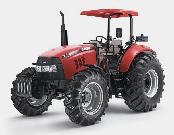 FARMALL 110A
 FARMALL 120A
 FARMALL 30C
 FARMALL 75C
 MAGNUM 280
________________________________________________________________________________________
 580E Backhoe
 580L Backhoe
 580N Backhoe
 580 Super L
 580SM Backhoe
________________________________________________________________________________________
________________________________________________________________________________________
 580SLE Backhoe
 580SN Backhoe
 580M Backhoe
 580 Super E
 580ST Backhoe
________________________________________________________________________________________
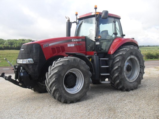 MAGNUM 310
 MAGNUM 340
 MAXXUM 110CVX
 MAXXUM 120CVX
 MAXXUM 125
________________________________________________________________________________________
 1394
1394 1455XL
 1494
1494 1594
1594 3230
3230________________________________________________________________________________________
 4210
4210 585XL
585XL 633
633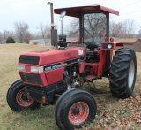 695XL
695XL 733
733________________________________________________________________________________________
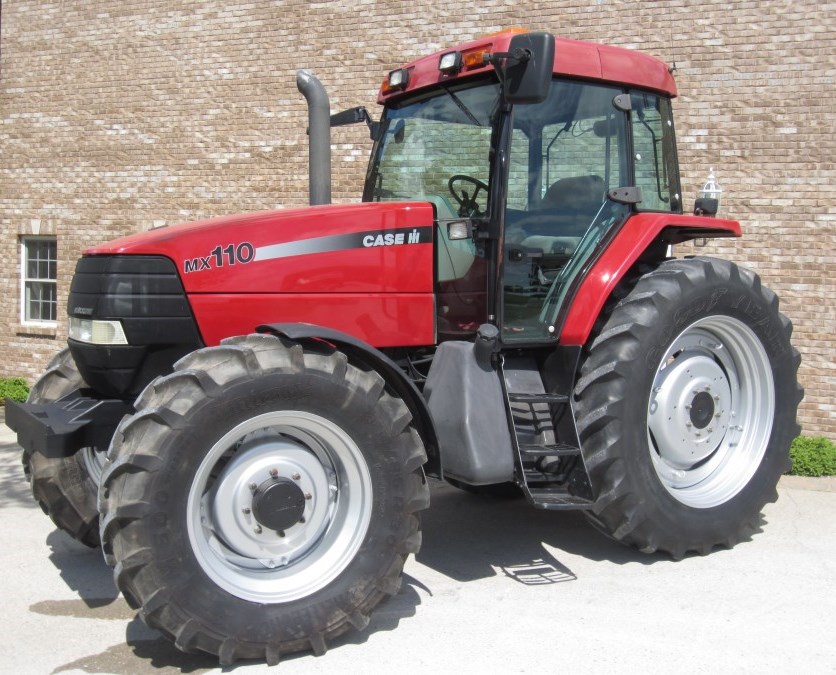 MX110
MX110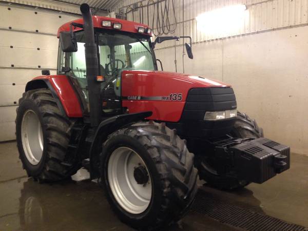 MX135
MX135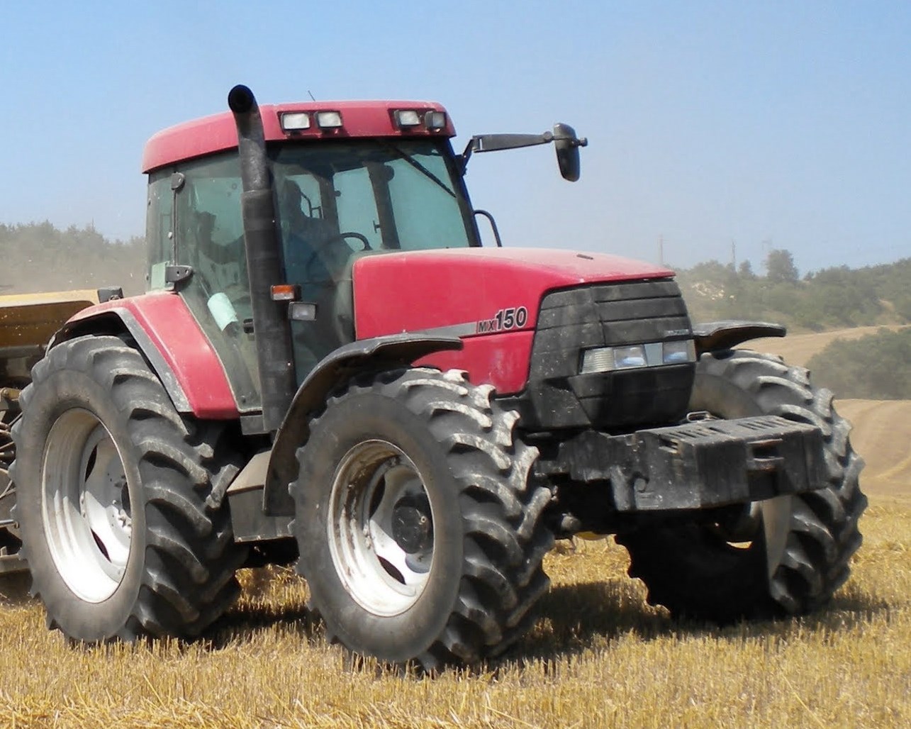 MX150
MX150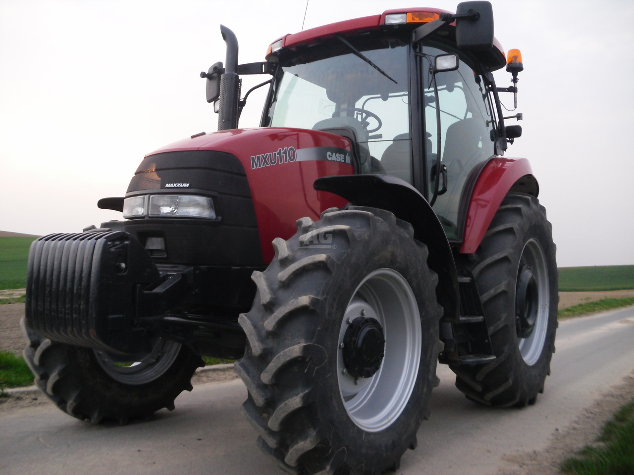 MXU110
 MXU135
________________________________________________________________________________________
 PUMA 175CVX
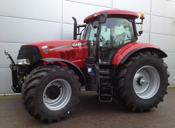 PUMA 185CVX
 PUMA 200CVX
 PUMA 240CVX
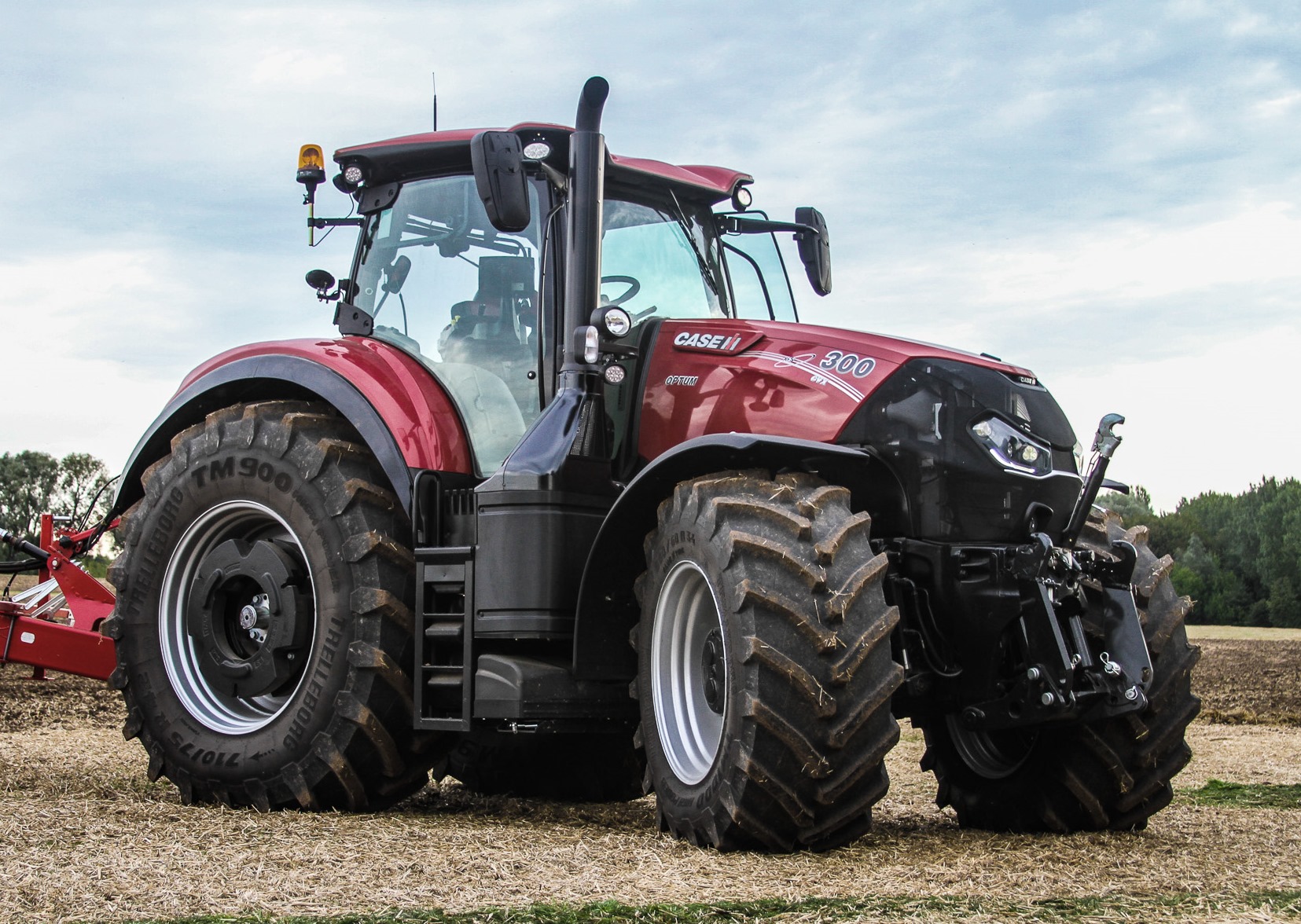 OPTUM 300
________________________________________________________________________________________
 FARMALL 50B
 FARMALL 95U
 FARMALL 125A
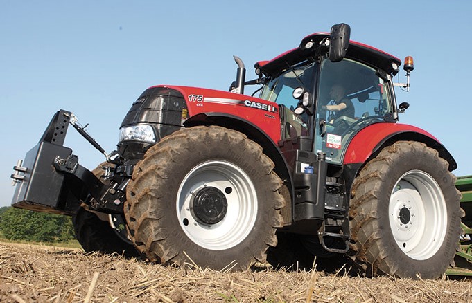
 PUMA 150
 PUMA 165
________________________________________________________________________________________
 MAGNUM 210
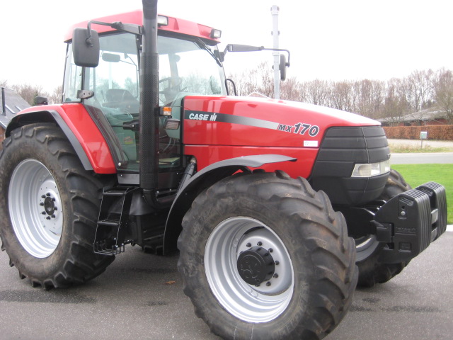 MX 170
 MAXXUM 150
 OPTUM 270
 MAGNUM 315
________________________________________________________________________________________
 FARMALL 70
 FARMALL 75N
 FARMALL 95C
 FARMALL 105N
 FARMALL 30B
________________________________________________________________________________________
| CASE IH FRONT END LOADERS SPECS |
 L103 Loader
 L104 Loader
 L105 Loader
 L106 Loader
 L107 Loader
________________________________________________________________________________________
 L108 Loader
 L130 Loader
 L160 Loader
 L300 Loader
 L340 Loader
________________________________________________________________________________________
 L350 Loader
 L360 Loader
 L530 Loader
 L540 Loader
 L545 Loader
________________________________________________________________________________________
 L550 Loader
 L555 Loader
 L560 Loader
 L565 Loader
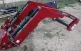 L570 Loader
________________________________________________________________________________________
 L575 Loader
 L720 Loader
 L730 Loader
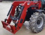 L735 Loader
 L740 Loader
________________________________________________________________________________________
 LRZ 95
 LRZ 100
 LRZ 120
 LRZ 130
 LRZ 150
________________________________________________________________________________________
 L745 Loader
 L750 Loader
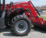 L755 Loader
 L760 Loader
 L765 Loader
________________________________________________________________________________________
 L770 Loader
 L775 Loader
 L780 Loader
 L785 Loader
 L795 Loader
________________________________________________________________________________________
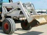 90 Loader
 890 Loader
 2200 Loader
 2250 Loader
 LX156 Loader
________________________________________________________________________________________