________________________________________________________________________________
Case IH 1494, 1594 Tractor Synchromesh transmission with shift selector levers - overhaul
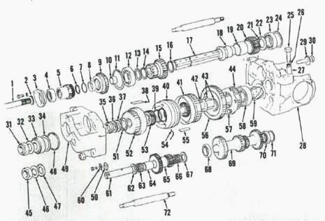
Fig.9. View of Case 1594, 1394, 1490, 1494, 1294 Tractor
12-speed synchromesh transmission
1.Front input shaft, 2.Snap ring, 3.Rear bearing carrier, 4.Bearing,
5.Input gear, 6.Snap ring, 7."O" ring, 8.Seal, 9.High /low slow gear,
10.Bushing, 11.Snap ring, 12.Bearing, 13.Spacer, 14.Snap ring, 15.Range
pinion, 16.Snap ring, 17.Rear input shaft, 18.Gear carrier, 19.Bushing,
20.Reverse idler gear, 21.Dowel pin, 22.Washer, 23.Bearing, 24.Shim,
25.Mounting boll, 26.Shim, 27.Bushing, 28.Rear end housing, 29.Tab
washer, 30.Bolt, 31.Locknut, 32.Washer, 33.Bearing, 34.Shim, 35.Spacer,
36.Spacer, 37.Spacer, 38.Bearing pad, 39.Snap ring, 40.Synchronizer,
41.Second gear, 42.Splined washer, 43.Split rings, 44.Shim, 46.Locknut
(used with from drive, 46.Tab washer (used with front drive), 47.Washer
(used with front drive), 48.Snap ring, 49.Front end housing, 50.Locating
plate, 51.Splined washer, 52.Third gear, 53.Front synchronizer gear,
54.Synchronizer spring, 55.Bearing pad, 56.First/reverse gear,
57.Retainer plate, 58.Bearing, 59.Pinion shaft, 60.Tab washer, 61.Idler
shaft, 62.Thrust washer, 63.Bearing, 64.Spacer, 65.Idler gear,
66.Bearing, 67.Thrust washer, 68.Bearing, 69.Countershaft assy,
70.Bearing, 71.Shim, 72.Spacer bar
Remove mounting bolts from input shaft rear bearing carrier (3) and
remove input shaft (1) assembly. Remove snap ring securing input shaft
front bearing carrier, then slide carrier from shaft.
Remove "O" ring and oil seal from front bearing carrier. Remove seal (8)
and "O" ring (7) from input gear (5). Remove snap rings (2 and 6) and
remove input gear and rear bearing carrier with bearing from input
shaft.
Drive roll pins from shift forks. Cover detent holes in end housing to
prevent detent balls and springs from flying out as shift rails are
removed. Keep each shift rail assembly together as they are removed. Use
a wooden wedge to lock differential assembly, then remove pinion shaft
nut (31). Pinion shaft nut has left-hand threads.
Remove four nuts from housing spacer rods, then withdraw front end
housing (49). Remove high/low slow gear (9). Remove idler shaft retainer
plate (50), then remove idler shaft (61) and idler gear (65). Remove
remaining bearing cups from end housing as necessary.
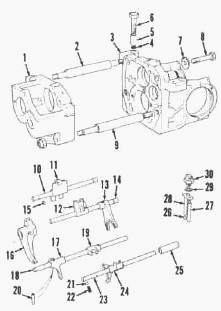
Fig.10. Case 1494, 1594 Tractor transmission components - End
plates, shift rods and shift
1.Front end plate, 2.Top spacer bar, 3.Rear end plate, 4.Shim,
5.Bushing, 6.Mounting bolts, 7.Tab washer, 8.Differential cap bolt,
9.Bottom spacer bar, 10.2nd & 3rd shift rod, 11.2nd & 3rd selector,
12.1st & reverse selector, 13.1st & reverse shift fork, 14.1st & reverse
shift rod, 15.Gear lock, 16.2nd & 3rd shift fork, 17.Shift fork,
slow/normal, 18.Slow/normal shift rod, 19.Selector, 20.Roll pin,
21.Detent ball, 22.Detent spring, 23.Range shift rod, 24.Shifter fork,
Hi-Lo, 25.Sleeve, 26.Steel ball, 27.Plunger, 28.Plunger, 29.Shim,
30.Safety start switch
Remove neutral start plungers (27 and 28) and detent balls (26) from
rear housing. Remove first and reverse shift rod assembly and second and
third shift rod assembly. Remove countershaft assembly (69) and rear
input shaft (17) assembly.
Press front bearing (12) off rear input shaft (17). Remove spacer (13),
snap ring (14) and range pinion gear (15). Press reverse idler gear
carrier (18), idler gear (20) and bearing (23) together off rear input
shaft. Use care not to lose dowel pin (21). Remove bushings (10 and 19)
from input shaft and reverse idler gear if necessary.
Remove first and reverse gear shift fork from pinion shaft assembly.
Remove spacer (35), shims (36), spacer (37), washer (51) and third gear
(52) from pinion shaft (59), Remove the six bearing pads (38), then lift
synchronizer (40) with shift fork off shaft.
Remove front and rear synchronizer gears, second gear (41) and the six
bearing pads (55). Remove splined washer (42) and split retainer ring
(43). Remove first and reverse gear (56). Remove pinion shaft retainer
plate (57) and shims (44). Remove pinion shaft (59) and press bearing
(58) off shaft.
Inspection of Case IH 1494, 1594
Tractor transmission parts
Clean and inspect all parts. Examine bearings and bushings for wear or
damage. If renewing a bearing, renew its respective mating cup. Gear
teeth should be evenly marked along length of teeth. If gear teeth have
been shaved or show irregular wear pattern, gear should be renewed along
with its mating gear.
If shifting into second or third has been difficult, examine
synchronizer friction surfaces and the synchronizer pads (38 and 55).
Slight radial clearance (looseness) in synchronizer is normal and the
pads should slide easily into their grooves without binding. No attempt
should be made to disassemble synchronizer assembly as individual
service parts are not available.

Fig.11
If jumping out of gear has been a problem and gears appear good, examine
fit of detent balls in grooves of shifter rails. Shift rail grooves
should have straight 60 degree sides and balls must be smooth with no
pits, rust or flat spots.
If necessary, grind bottom of groove, taking care not to damage sides,
until detent ball has sufficient
clearance at bottom of groove. Check detent spring length which should
be 31.75 mm (1.250 inches).
Examine all thrust washers and spacers for excessive wear or damage and
renew as necessary. If pinion shaft, end housings, center housing, or
pinion shaft bearings are renewed, pinion shaft protrusion must be set
before Case IH 1494, 1594 Tractor transmission reassembly.
Pinion shaft assembly
With pinion shaft (59), bearing (58) and correct thickness of shims (44)
in position, install retainer plate (57) and tighten retaining bolts to
40 N-m (30 ft.-lbs.) torque.
Install first/reverse gear (56) with shift fork groove toward retainer
plate (57). Install split rings (43) and spacer (42). Apply grease to
the six bearing pads (55) and install pads in splines of pinion shaft
(59).
Install:
- second gear (41) on pinion shaft and bearing pads with gear side
toward retainer plate (57).
- rear synchronizer gear (not shown) with slotted side against second
gear (41).
- snap ring (39) and front synchronizer gear (53) with slotted side of
gear away from snap ring (39). Make certain front and rear synchronizer
splines (teeth) are aligned. Place shift fork in groove on synchronizer,
then install synchronizer and shift fork together making certain shift
fork slides easily on spacer bar. Apply grease to the six bearing pads
(38) and install in splines of pinion shaft (59).
- third gear (52) on pinion shaft and bearing pads with gear side
towards threaded end of pinion shaft.
- splined washer (51) and spacer (37). Do Not install shims (36) or
spacer (35) at this time. Place first/reverse gear shift fork in groove
of first/reverse gear (56).
Rear input shaft assembly
Press bushing (10) into rear input shaft (17). Press bushing (19) into
reverse idler gear (20).
Install:
- snap ring (16) in groove of rear input shaft at bushing
carrier(18)end.
- bushing carrier (18) on rear input shaft (17) with largest outside
diameter next to snap ring (16). Lubricate and install reverse idler
gear (20).
- dowel pin (21) if so equipped.
- thrust washer (22) with flat side toward reverse idler gear. Heat rear
bearing to 120°C (250°F) maximum, then install onto shaft.
- high/low range gear (15) with larger diameter gear on shaft first.
- snap ring (14) and spacer (13). Heat front bearing (12) to 120°C
(250°F) maximum, then install onto shaft.
- input shaft assembly in position on rear housing (28) minus shims
(24).
- front housing (49) and tighten spacer bar nuts to 95 N-m (70 ft.-lbs.)
torque. Mount dial indicator on front housing so probe touches end of
rear input shaft. Move shaft up and down and measure end play. Correct
end play is 0.05-0,43 mm (0.002-0.017 inch). Remove front housing and
the rear input shaft assembly. Assemble and install shims (24) as
necessary in rear housing bearing bore to obtain correct end play.
Reinstall rear input shaft assembly.
Countershaft assembly
Heat bearings (68 and 70) to 120°C (250°F) maximum before installing on
countershaft (69).
Install:
- bearing cup in rear housing without shims (71). Position countershaft
in rear end housing.
- front housing and tighten spacer bar nuts to 95 N-m (70 ft.-lbs.)
torque.
Mount a dial indicator on rear housing so probe contacts face of rear
gear of countershaft. Move shaft up and down and measure end play.
Specified end play is 0.05-0.10 mm (0.002-0.004 inch). Remove front end
housing, countershaft and rear bearing cup.
- shims (71) as necessary to provide desired end play, then reinstall
bearing cup and countershaft.
- first/reverse and second/ third shift rail assemblies.
Front housing assembly
Install:
- bearings (63 and 66) and spacer (64) into range idler gear (65).
Bearing cages should be slightly below end surface of range idler gear
when installed.
- idler gear assembly with a thrust washer (62 and 67) at each end.
- idler shaft (61) and secure with locating plate (50) and mounting
bolt. Position high/low slow gear (9) in front housing with shift fork
groove up.
- front housing assembly onto Case IH 1594, 1494 Tractor transmission
making certain rear input shaft goes through high/low slow gear.
- new spacer rod nuts and tighten to 95 N-m (70 ft.-lbs.) torque.
Pinion shaft end play
Install:
- original shim pack (36) removed during disassembly plus an additional
0.25 mm (0.010 inch) thick shim.
- shoulder washer (35) with flat side against shims.
- bearing cone, washer and nut on pinion shaft and tighten nut to 270
N-m (200 ft.-lbs.) torque.
Position a dial indicator on front housing so probe contacts end of
pinion shaft. Move pinion shaft up and down and measure end play.
Remove nut and bearing, then reduce shim thickness as necessary to
provide zero end play to 0.05 mm (0.002 inch) preload. Reassemble using
a new nut and tighten nut to 270 N-m (200 ft.-lbs.) torque.
Front input shaft assembly
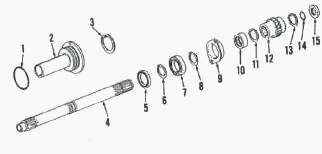
Fig.12. View of front Input shaft assembly
1."O" ring, 2.Support sleeve, 3.Snap ring, 4.Front input shaft, 5.Seal,
6.Snap ring, 7.Bearing, 8.Snap ring, 9.Rear bearing carrier, 10.Bearing,
11.Snap ring, 12.Input gear, 13.Snap ring, 14."O"ring, 15.Seal
Install:
- new needle bearing (10), if removed, into retainer (9) using special
tool or other suitable tool.
- oil seal (5) in support sleeve (2) and place "O" ring (1) on sleeve.
Place input gear (12) onto shaft.
- snap ring (13).
- new "O" ring (14) and oil seal (15) into input gear.
- snap ring (11) against input gear. Slide rear bearing carrier assembly
(9) onto input shaft.
- front carrier bearing (7) and retaining rings onto shaft. Lubricate
support sleeve seal, then slide sleeve over the shaft and onto front
bearing.
- snap ring (3) in support sleeve.
Shift rods and detent assembly
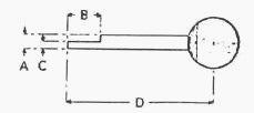
Fig.13
Springs and aid for Installing detent balls end fabricate a tool using
the following dimensions A - 9,5 mm (0.375 inch), B - 15,8 mm (0.625
inch), C - 4,8 mm (0,187 inch), D - 150 mm (6.0 inch)
To facilitate installation of detent balls and springs, fabricate an
installation tool as shown in Figure. Install detent ball and spring for
first/reverse shift rod using tool. Push detent ball down with tool
while moving shift rod into rod bore as shown.
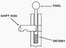
Fig.14. When Installing shift rods and detents, use tool shown
to push detent ball and spring
Install:
- shift interlock plug by placing in position through second/third gear
shift rod bore. With interlock plug in position, install detent ball and
spring and second/third shift rod.
- remaining shift rods, forks, detent springs and balls in similar
manner.
- roll pins in shift forks and rods. Install neutral start switch balls,
rods, plate and switch.
- input shaft assembly and tighten rear bearing retainer mounting bolts
to 23-27 N-m (17-20 ft.-lbs.) torque.
Shift transmission and range section through all gears and check to be
certain all gears and detents work properly.
________________________________________________________________________________
________________________________________________________________________________________
| CASE IH TRACTORS SPECIFICATIONS |
________________________________________________________________________________________
________________________________________________________________________________________
________________________________________________________________________________________
________________________________________________________________________________________
________________________________________________________________________________________
________________________________________________________________________________________
________________________________________________________________________________________
________________________________________________________________________________________
________________________________________________________________________________________
________________________________________________________________________________________
________________________________________________________________________________________
| CASE IH FRONT END LOADERS SPECS |
________________________________________________________________________________________
________________________________________________________________________________________
________________________________________________________________________________________
________________________________________________________________________________________
________________________________________________________________________________________
________________________________________________________________________________________
________________________________________________________________________________________
________________________________________________________________________________________
________________________________________________________________________________________
 CASE IH SPECS
 J.I. CASE SPECS
 PROBLEMS
 LOADERS
 FARMALL 110A
 FARMALL 120A
 FARMALL 30C
 FARMALL 75C
 MAGNUM 280
 580E Backhoe
 580L Backhoe
 580N Backhoe
 580 Super L
 580SM Backhoe
 580SLE Backhoe
 580SN Backhoe
 580M Backhoe
 580 Super E
 580ST Backhoe
 MAGNUM 310
 MAGNUM 340
 MAXXUM 110CVX
 MAXXUM 120CVX
 MAXXUM 125
 1394
1394 1455XL
 1494
1494 1594
1594 3230
3230 4210
4210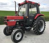 585XL
585XL 633
633 695XL
695XL 733
733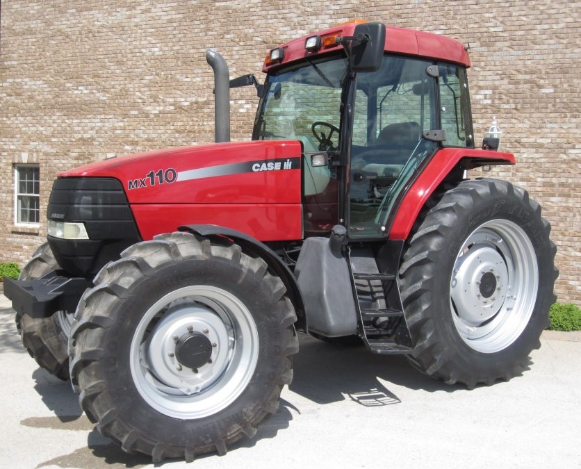 MX110
MX110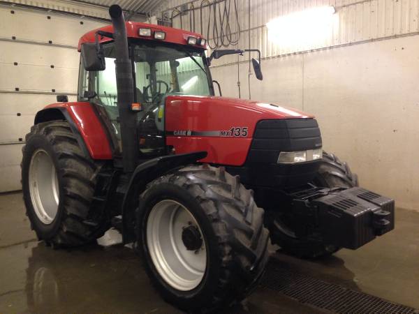 MX135
MX135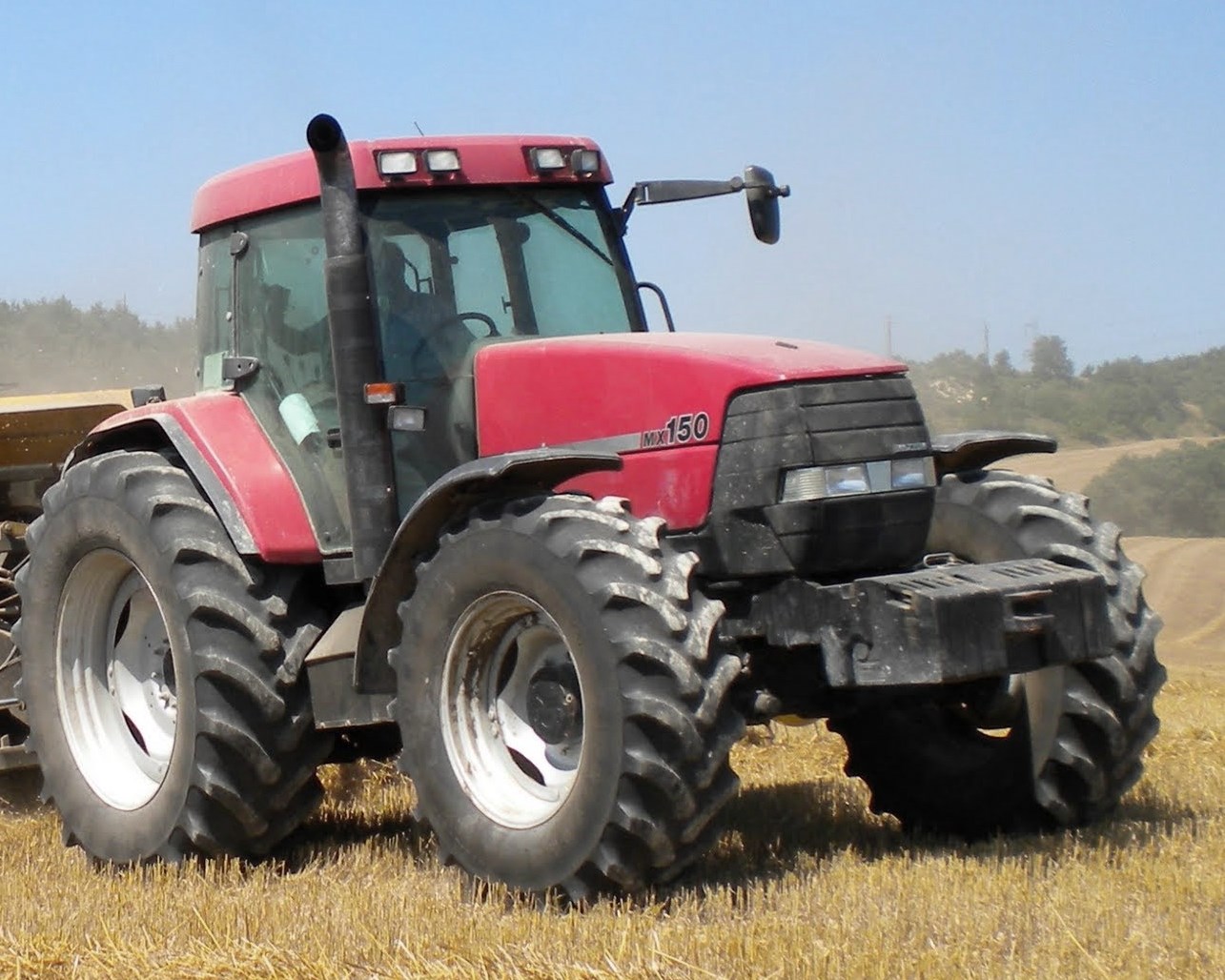 MX150
MX150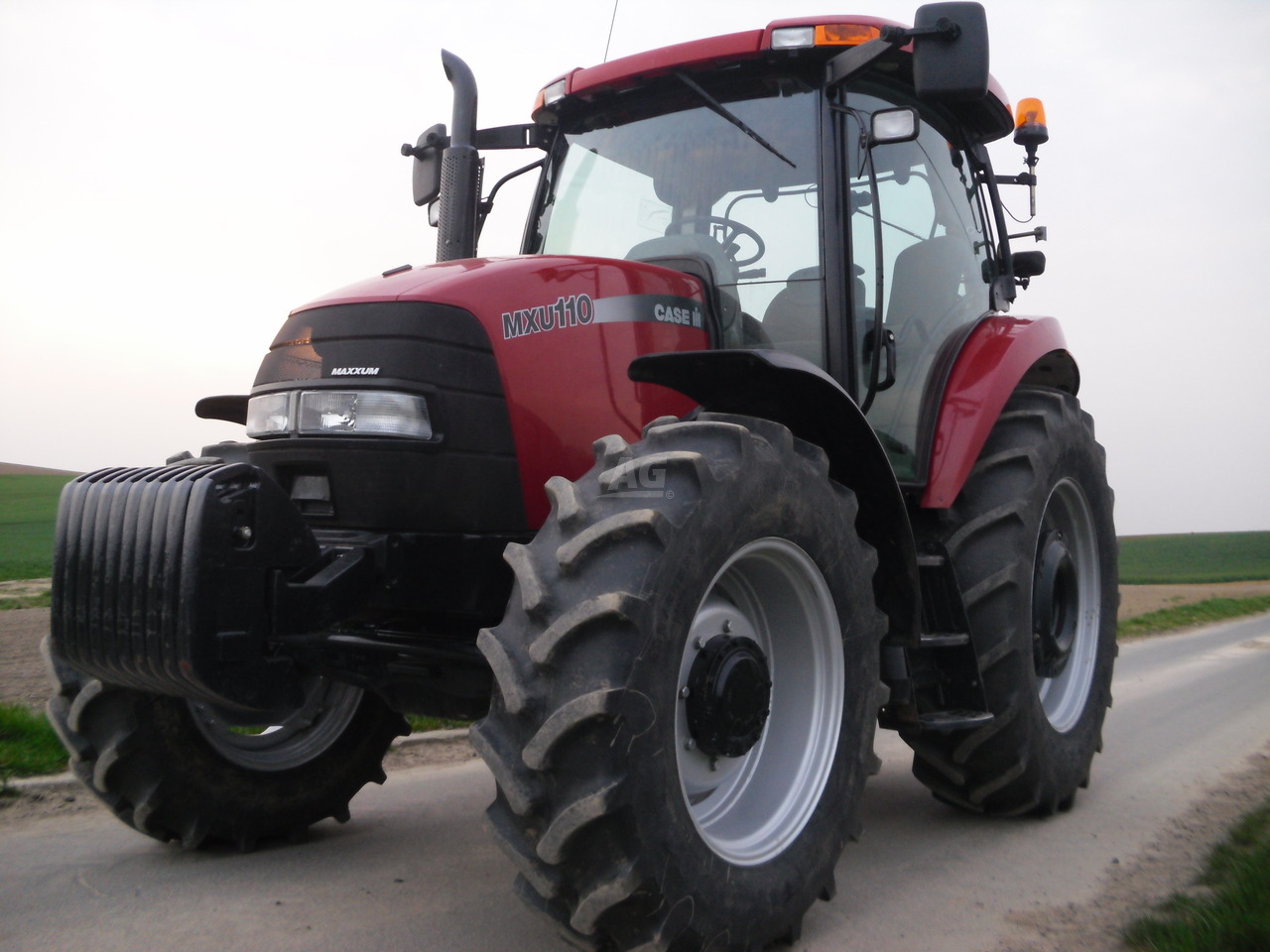 MXU110
 MXU135
 PUMA 175CVX
 PUMA 185CVX
 PUMA 200CVX
 PUMA 240CVX
 OPTUM 300
 FARMALL 50B
 FARMALL 95U
 FARMALL 125A
 PUMA 150
 PUMA 165
 MAGNUM 210
 MX 170
 MAXXUM 150
 OPTUM 270
 MAGNUM 315
 FARMALL 70
 FARMALL 75N
 FARMALL 95C
 FARMALL 105N
 FARMALL 30B
 L103 Loader
 L104 Loader
 L105 Loader
 L106 Loader
 L107 Loader
 L108 Loader
 L130 Loader
 L160 Loader
 L300 Loader
 L340 Loader
 L350 Loader
 L360 Loader
 L530 Loader
 L540 Loader
 L545 Loader
 L550 Loader
 L555 Loader
 L560 Loader
 L565 Loader
 L570 Loader
 L575 Loader
 L720 Loader
 L730 Loader
 L735 Loader
 L740 Loader
 LRZ 95
 LRZ 100
 LRZ 120
 LRZ 130
 LRZ 150
 L745 Loader
 L750 Loader
 L755 Loader
 L760 Loader
 L765 Loader
 L770 Loader
 L775 Loader
 L780 Loader
 L785 Loader
 L795 Loader
 90 Loader
 890 Loader
 2200 Loader
 2250 Loader
 LX156 Loader