________________________________________________________________________________
John Deere 5225, 5325, 5425, 5525, 5625 PTO and Hitch
- JD 5225-5625 Engine
- JD 5225-5625 PTO and Hitch
- JD 5225-5625 Drivetrain
- JD 5225-5625 Hydraulic System
JD 5225, 5325, 5425,
5525, 5625 PTO
Reversing 540/1000 RPM PTO Stub Shaft
Power Take-Off stub shaft has six splines for operating 540-rpm
implements and 21 splines for 1000-rpm implements. A flattened area on
the stub shaft facilitates
snap ring removal and installation.
- Align snap ring ends with access flat. Remove snap ring and pull out
stub shaft.
- Clean stub shaft thoroughly and coat with grease. Be sure end bore is
clean when installing shaft for 1000-rpm operation.
- Turn stub shaft end-for-end and insert in Power Take-Off housing until
snap ring groove is visible.
- Install snap ring. Move shift lever to agree with stub shaft position.
Attaching PTO (Driven Implement)
- Turn key to STOP position to shut off engine.
- Put drawbar in extended position. If implement will be connected to
3-point hitch, be sure drawbar will not interfere. Fully retract drawbar
or remove it if necessary.
Install drawbar lock pin.
- Attach implement to John Deere 5225, 5325, 5425, 5525, 5625 tractor
(drawbar or 3-point hitch) before connecting Power Take-Off driveline.
Raise hitch to full-up
(transport) position if it is not to be used.
- Rotate PTO shield up for clearance. With engine off, turn PTO shaft by
hand to line up splines. Connect driveline to PTO shaft. Pull out on
shaft to be sure
driveline is locked to PTO shaft. Return Power Take-Off shield to down
position.
- Check that all shields are in place and in good condition. Never
operate PTO unless master shield is properly installed. WITH ENGINE
STOPPED, check integral
shields on driveline by making sure they rotate freely on shaft.
Lubricate or repair as necessary. Check for interference.
Selecting Correct PTO Speeds
540/540E Operation
- For standard 540 PTO operation (load requiring full engine power),
pull lever back to 540 position.
- For economical PTO operation (lighter load), push lever forward to
540E position. In economical mode, engine is run at lower rpm to
conserve fuel and reduce
overall operating noise while still turning PTO shaft at 540 rpm.
- With PTO shift lever in 540E position, engine fast idle speed is
limited to 1700 rpm.
- Same shift lever design is used for both 540/540E PTO and 540/1000
PTO.
540/1000 Operation
- Power Take-Off conversion kits are available for most tractors. For
540 rpm PTO operation pull lever back to 540 position.
- When PTO stub shaft is installed for 540 rpm implement, a mechanical
interlock prevents shifting from 540 rpm to 1000 rpm setting.
- Stub shaft must be reversed from 540 to 1000 rpm position before
moving shift lever to 1000 rpm position.
- For 1000 rpm PTO operation, push lever forward to 1000 position.
Operating JD 5225, 5325, 5425, 5525, 5625 Tractor PTO
Engine will not start if PTO lever is engaged. If equipped with EH PTO
switch, engine will start with switch up (engaged), but PTO shaft will
not rotate until switch is
reset.
Depress clutch pedal, start engine and push hand throttle lever forward
until tachometer indicates PTO rated speed: 540E - 1700 RPM / 540 - 2400
RPM (full
power) / 1000 - 2400 RPM (full power). When in 540E position, engine
speed is mechanically limited to a maximum of 1700 rpm. 540E operation
will not engage if
engine speed is above 1700 rpm. Both 540 rpm and 1000 rpm PTOs operate
at same engine speed: 2400 rpm. PTO is engaged or disengaged without
depressing
clutch pedal.
Engage Power Take-Off
- Lever Operated: Move control lever inward and forward to engage PTO.
- EH Switch Operated: Lift switch knob up to "I" position to engage PTO.
- PTO indicator will light when PTO is engaged.
- A warning alarm will sound if operator leaves seat with PTO engaged.
If engine is stopped while PTO is engaged: 1) Lever Operated PTO -
Disengage PTO, restart engine and engage PTO. 2) EH Switch Operated PTO
- Restart
engine, depress and lift switch knob to reset and engage PTO.
Disengage Power Take-Off
- Lever Operated: Pull lever back to latch stop position to disengage
PTO.
- Lever latch stop prevents accidental engagement of the PTO.
- EH Switch Operated (if equipped):Push switch knob down to "O" position
to disengage PTO.
- PTO brake automatically engages when PTO is disengaged.
Adjusting 540/540E PTO Lever and Linkage
- Remove spring locking pin from upper control cable. Disconnect yoke
from arm.
- Rotate arm to the rear position (clockwise). Move 540/540E PTO lever
to the forward position.
- Loosen jam nut from yoke. Adjust yoke until spring locking pin aligns
with hole in yoke and arm. Install spring locking pin and tighten jam
nut to yoke.
- Start engine and move throttle lever until 1700 rpm is indicated on
tachometer. Do not move throttle lever after 1700 rpm is reached.
- Shut engine off with throttle lever positioned at 1700 rpm. Make sure
throttle linkage at fuel injection pump does not move during the next
step.
- Slowly move the 540/540E control lever fully forward. Make sure
throttle linkage does not move forward during this step.
- If linkage moves forward, loosen jam nut and turn adjustment nut
counterclockwise until a gap of 6 mm (0.25 in.) is between adjustment
nut and plate.
- Loosen jam nut and turn adjustment nut until seated against plate.
- Hold adjustment nut using a wrench, and tighten jam nut.
Adjusting PTO Clutch Lever Linkage (Mechanical PTO Lever)
Straddle Mount and Hi-Crop
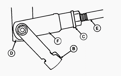
A - Power Take-Off Clutch Lever, B - Clip Pin, C - Jam Nut, D - Arm, E -
Rod, F - Clevis
- Move PTO clutch lever (A) to rearward (disengaged) position. Loosen
jam nut (C) from rear of clevis (F). Remove clip pin (B).
- Adjust length of rod (E) so clip pin (B) can be inserted with rod
pulled forward and arm (D) pulled rearward to eliminate free play.
- Lengthen rod (E) by 1/2 turn of clevis (F) to provide a slight amount
of lever free play.
- Reinstall clip pin (B) in clevis (F) and arm (D). Check for equal
thread engagement at each end of PTO clutch rod.
- Jam nut at rear (not shown) can be loosened and rod turned to equalize
thread engagement (PTO adjustment is not affected).
- Tighten jam nuts (C) at each end of rod.
Cab and IOOS
- Move PTO clutch lever to rearward (disengaged) position.
- Pull rubber floor mat away from left side of floor.
- Remove access cover. Loosen jam nut at rear of yoke.
- Remove cap screw and nut disconnecting yoke from PTO clutch arm.
- Move PTO clutch arm rearward to engaged position. Back off PTO clutch
arm approximately 1.2 cm (0.5 in.) and hold in position.
- Install cap screw back into yoke and turn yoke clockwise or
counterclockwise until yoke lines up with PTO clutch arm.
- Connect yoke to PTO clutch arm with cap screw and install nut. Tighten
jam nut against yoke.
- Install access cover. Pull rubber floor mat back over access cover.
5225, 5325, 5425, 5525, 5625 John Deere Hitch
Using Mechanical Rockshaft Position Control
Use position control lever to control hitch movement and depth:
Transport - For transport of implements and end of field turn-around,
pull control lever fully rearward for both load and non-load sensing
usage.
Constant Depth - For constant depth of implements on level terrain and
for non-ground engaging implements such as spreaders or sprayers, put
position control
lever at desired depth. Operate implement for a few minutes to determine
proper depth or height. Lift tab and slide stop against position control
lever. Turn tab to
tighten and press down to lock stop in place. Rockshaft will return to
the same position each time control lever contacts the stop.
Float - For float operation for implements with skids or depth gauge
wheels designed to carry full implement weight, push both position and
draft control levers all
the way forward, so implement can follow ground contour. Lift links can
be adjusted for lateral float.
Using Mechanical Draft Control
The rockshaft is equipped with variable draft control system:
- Operating with a fully mounted implement in hill and swale terrain,
the implement will rise and lower to follow the ground contours while
maintaining a nearly
constant depth.
- Operating in varying soil conditions, the implement is raised slightly
to get through tough spots so you do not have to shift to a lower gear.
Change draft sensitivity ranges by repositioning the center link.
For draft load sensing operation:
- Pull control lever to its fully rearward position and push the draft
control lever to the fully forward (least draft) position.
- With John Deere 5225, 5325, 5425, 5525, 5625 tractor moving, push
control lever forward to set implement operating depth.
- Set position control lever stop. The operating depth set up will
prevent the rockshaft from lowering all the way when the tractor begins
to slip.
- Pull draft sensing lever rearward until desired draft sensing
sensitivity is obtained.
- To slightly raise implement (for getting through slippery spots in a
field), push control lever past the draft control setting.
- Pull control lever fully rearward to raise the hitch at the end of the
field.
Using EH External Raise and Lower Switches
When using the fender mounted switches, the rockshaft raises and lowers
at a slower rate, and the height and depth settings are ignored. Fender
switches are
disabled when hitch is in transport position.
Press and hold switch to move rockshaft: RAISE implement with top switch
/ LOWER implement with bottom switch.
Once either switch is activated, the rockshaft is prevented from moving
accidentally.
To reactivate the rockshaft, return to the operator station:
- Move hitch control lever to position that corresponds to position of
the draft links.
- Actuate raise/lower switch.
Adjusting Raise Height - Control the implement height with knob: For
minimum height, turn COUNTERCLOCKWISE. For maximum height, turn
CLOCKWISE.
Adjusting Rate-of Drop
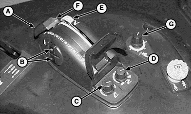
A - Hitch Control Lever, B - Raise/Lower Switch, C - Height-Limit
Control, D - Rate-of-Drop Control Knob, E - Depth Stop Wheel, F - Hitch
Control Lever, G -
Load/Depth Control Knob
Fully lowering implement should take at least 2 seconds.
Control the speed the rockshaft and mounted implement lowers with knob
(D):
- To slow rate-of-drop, turn knob COUNTERCLOCKWISE.
- For faster rate-of-drop, turn knob CLOCKWISE.
Adjusting Depth Stop
- Push down and rotate wheel (E) to set stop to the desired working
depth.
- Push control lever (F) forward to contact the stop to return the
implement to the indicated working depth.
- To lower hitch below the preset depth, lift and push the control lever
past the stop.
Using Float Control
- For rockshaft-controlled implements with a gauge wheel, implements can
move freely up and down to follow ground contours independent of the JD
5225, 5325,
5425, 5525, 5625 tractor.
- Turn control knob (G) to position control detent and push hitch
control lever (F) as far forward as it will go.
- Adjust lift links for lateral float.
Adjusting Load/Depth EH Controls
Hitch has two operating modes: Detent control position / Draft control
positions.
Position Control Setting - With load/depth knob in detent control
position, the implement is held at the selected position.
Using Draft Control
Turn load/depth knob to one of five draft settings, to control depth and
load, depending on implement and field or soil conditions:
- Turn COUNTERCLOCKWISE to reduce draft response.
- Turn CLOCKWISE to increase draft response.
With the control turned to a higher number, the implement is raised as
resistance (soil density) increases and lowered as resistance decreases;
typical settings.
Integral Ripper/Subsoiler - 1-3
Integral Chisel Plow - 2-4
Semi-Integral Moldboard Plow - 2-4
Integral Moldboard Plow - 3-5
Integral Field Cultivator - 4-5
Preparing Implement
When attaching Category I implements to the 5225, 5325, 5425, 5525, 5625
John Deere tractor, sway bars may need adjustment to prevent binding and
limiting full
raise of the hitch. Category I, 3-Point Hitch is narrower and is used
for smaller implements than Category II implements. Category II
implements should have the top
hole of the implement mast located 483 mm (19 in.) above the lower pins.
Drill another hole in top mast or extend top mast if necessary.
Converting Category II Hitch to Category I
Center link end is sized for Category II implement attaching pin. If
Category I implements are to be used, the Category II hitch can be
converted as follows: Insert
reducer bushing in center link end. Smaller implement mast pin is also
needed when bushing is installed. Rotate balls in draft link ends to fit
over implement pins.
Positioning Center Link
The center link attaching bracket has holes which allow three different
positions for attaching the center link. The position affects the draft
sensing sensitivity.
Should the following conditions occur, move center link to indicated
holes to correct.
- Excessive hitch activity or hunting occurs in draft control operation
- Use Upper or Middle Holes.
- Rear of implement rises too much when lifted. The implement weight
which can be lifted is reduced slightly with center link attachment in
lower holes - Use Upper
or Middle Holes.
- Rear of implement drags the ground - Use Middle or Lower Holes.
- Draft control lever range is too small - Use Middle or Lower Holes.
- Hitch seems unresponsive in draft control operation and allows engine
speed to drop too far before raising rockshaft - Use Middle or Lower
Holes.
Implements with Category I mast height 457 mm (18 in.) will normally use
the lower two attaching holes and implement with Category II mast height
483 mm (19 in.)
will use the upper two holes.
Adjusting Hitch Side Sway
- Check implement operator's manual for instruction on whether to allow
side sway.
- If sway is desired, install pin in outer hole, ensuring it goes
through slot of inner sliding member.
- If sway is not desired, move draft link to desired position.
- Install pin in one of five fixed position holes that lines up with one
of the holes (not slot) of the inner member.
- Adjust opposite side sway bar to same position.
Leveling the 5225, 5325, 5425, 5525, 5625 Hitch
Lower implement to take weight off hitch and adjust center link to level
implement front-to-rear. Dont attempt to overextend center link beyond
limits of locking clip
or lift links past the stops. Link body threads could be damaged.
Maximum adjustment range of the center link can only be obtained if the
ends are positioned
equally within the body when attached to an implement. On later model
tractors make sure the center link does not unscrew past the extension
limit groove cut into
threads. Unlatch locking clip. Rotate center link body: CLOCKWISE to
lengthen center link. COUNTERCLOCKWISE to shorten center link. Latch
locking clip.
Adjust right link to level implement side-to-side. Lift locking handle
and rotate 90° to engage slot onto roll pin. Turn locking handle:
CLOCKWISE to raise draft link.
COUNTERCLOCKWISE to lower draft link. Lift handle and rotate 90° to
engage slot onto locking tab of lower body to prevent change of
adjustment during
operation.
Left lift link is also adjustable in length to accommodate two different
length right lift link assemblies used, depending on tire size. The
following adjustments will
provide optimum hitch leveling: Right lift link, center threaded section
measures 316 mm (12-7/16 in.) long: Adjust the left lift link to 550 mm
(21-5/8 in.) from pin-to-pin (lateral float locked out).
Right lift link, center threaded section measures 266 mm (10-1/2 in.)
long: Shorten the left lift link to 450 mm (17-7/16 in.). To change the
left lift link length: Remove
upper lift link pin. Rotate the upper end assembly: CLOCKWISE to
shorten. COUNTERCLOCKWISE to lengthen. Install upper pin and locking
pin.
Adjusting Lateral Float
To allow draft link to rise slightly as implement follows ground
contour, put pin head and rectangular washer in vertical position.To
hold implement rigid, place pin
head and rectangular washer in horizontal position.
Float position: Hitch-mounted implements (cultivator or mower), which
have ground gauging skids or wheels which may cause the implement to
twist relative to the
tractor. Rigid position: Plows and ground engaging implements that
should not twist relative to the tractor.
- JD 5225-5625 Engine
- JD 5225-5625 PTO and Hitch
- JD 5225-5625 Drivetrain
- JD 5225-5625 Hydraulic System
________________________________________________________________________________
________________________________________________________________________________________
________________________________________________________________________________________
________________________________________________________________________________________
________________________________________________________________________________________
________________________________________________________________________________________
________________________________________________________________________________________
________________________________________________________________________________________
________________________________________________________________________________________
________________________________________________________________________________________
________________________________________________________________________________________
________________________________________________________________________________________
________________________________________________________________________________________
________________________________________________________________________________________
________________________________________________________________________________________
________________________________________________________________________________________
________________________________________________________________________________________
________________________________________________________________________________________
________________________________________________________________________________________
________________________________________________________________________________________
________________________________________________________________________________________
________________________________________________________________________________________
________________________________________________________________________________________
________________________________________________________________________________________
________________________________________________________________________________________
________________________________________________________________________________________
________________________________________________________________________________________
________________________________________________________________________________________
________________________________________________________________________________________
________________________________________________________________________________________
________________________________________________________________________________________
________________________________________________________________________________________
________________________________________________________________________________________
________________________________________________________________________________________
________________________________________________________________________________________
________________________________________________________________________________________
________________________________________________________________________________________
________________________________________________________________________________________
________________________________________________________________________________________
________________________________________________________________________________________
________________________________________________________________________________________
________________________________________________________________________________________
________________________________________________________________________________________
________________________________________________________________________________________
________________________________________________________________________________________

 JD SPECS
 JD LOADERS
 JD MAINTENANCE
 JD INSTRUCTIONS
 JD PROBLEMS
 JD 2025R
 JD 3039R
 JD 4044R
 JD 4105
 JD 4720
 420 Loader
 419 Loader
 510 Loader
 512 Loader
 520 Loader
 520M Loader
 540M NSL
 540 Loader
 440R Loader
 H180 Loader
 JD 5045E
 JD 5085E
 JD 5100M
 JD 6105R
 JD 6120M
 JD 6155M
 JD 6195R
 JD 6210R
 JD 7210R
 JD 7250R
 JD 7310R
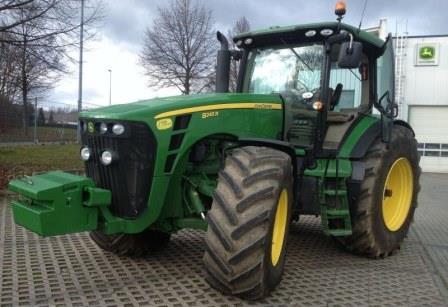 JD 8245R
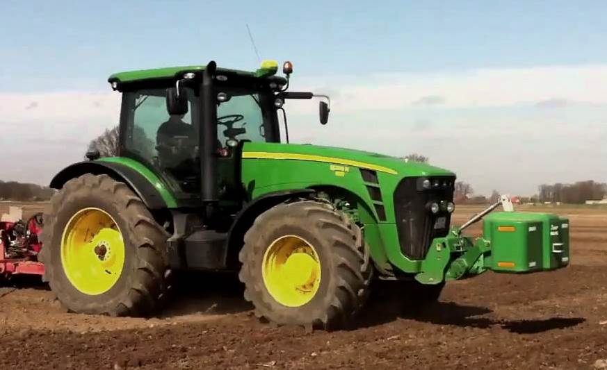 JD 8295R
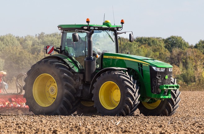 JD 8370R
 JD 9370R
 120R Loader
 D120 Loader
 H120 Loader
 45 Loader
 200CX Loader
 D160 Loader
 D170 Loader
 H160 Loader
 H165 Loader
 H240 Loader
 210 Loader
 220R Loader
 300E Loader
 300X Loader
 300CX Loader
 JD 9420R
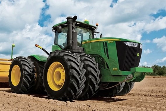 JD 9510R
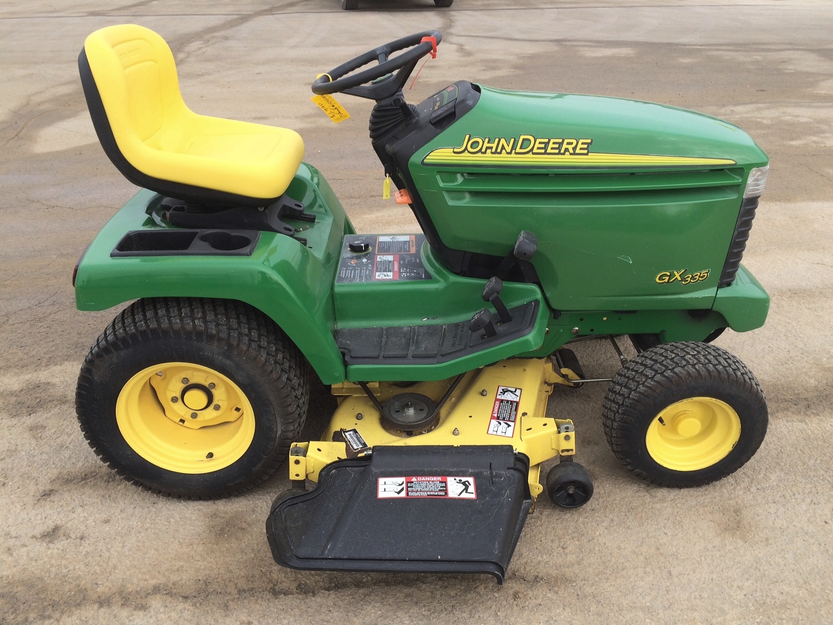 JD GX335
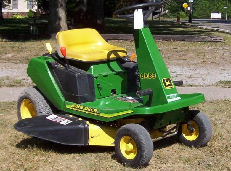 JD GX85
 JD LA105
 JD 5065M
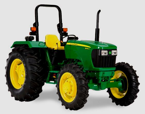 JD 5055D
 JD 5115R
 JD 5105M
 JD 6110R
 JD 6130D
 JD 6225
 JD 7530
 JD 4044M
 JD 7185J
 300 Loader
 300R Loader
 320R Loader
 400E Loader
 410 Loader
 430 Loader
 460 Loader
 521 Loader
 531 Loader
 541 Loader
 551 Loader
 631 Loader
 651 Loader
 661 Loader
 603R Loader
 JD D130
 JD D160
 JD 325
 JD 335
 JD 345
 JD 2520
 JD 3005
 JD 3720
 JD 1025R
 JD 3033R
 JD 5090EL
 JD 5100MH
 JD 5075GV
 JD 6090RC
 JD 6110B
 623R Loader
 643R Loader
 731 Loader
 746 Loader
 751 Loader
 533 Loader
 583 Loader
 633 Loader
 653 Loader
 683 Loader
 H260 Loader
 663R Loader
 663 Loader
 683R Loader
 753 Loader
 JD 6125J
 JD 6150RH
 JD 6210J
 JD 7195J
 JD 8310
 JD 6325
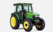 JD 5525
 JD 5083EN
 JD 5100GN
 JD 5125R
 210C Backhoe
 300D Backhoe
 310G Backhoe
 410G Backhoe
 710G Backhoe
 80 Loader
 100 Loader
 146 Loader
 148 Loader
 158 Loader
 168 Loader
 175 Loader
 522 Loader
 542 Loader
 540R Loader
 562 Loader
 563 Loader
 673 Loader
 741 Loader
 L108 Automatic
 L120 Automatic
 LA110 Automatic
 LA120 Automatic
 LA150 Automatic
 LT155
LT155 LT160 Automatic
 LT180 Automatic
 LTR180
 X165
X165 E100
E100 E120
E120 E150
E150 LTR166
 LA135
LA135 LA165
LA165 LX277
LX277 LX288
LX288 LX255
LX255 S240
S240 GT235
GT235 G110 Automatic
 JD 3203
 JD 5520
 JD 316
 JD 420
 JD 425
 JD 445
 JD_5050D
 X300
X300 X304
X304 X310
X310 X110 Automatic
 H310 Loader
 H340 Loader
 H360 Loader
 H380 Loader
 H480 Loader
 240 Loader
 245 Loader
 260 Loader
 265 Loader
 600R Loader
 620R Loader
 640R Loader
 660R Loader
 680R Loader
 JD_5039D
 X146R
X146R X360
X360 X155R
X155R X140 Automatic
 X350
X350 X380
X380 X500
X500 X590
X590 X700
X700 3036E
3036E 2038R
2038R 3038R
3038R 4049M
4049M JD 4100
 X738
X738 X740
X740 X748
X748 X749
X749 X950R
X950R JD 4510
 5045D
5045D 5050E
5050E 5060E
5060E 5078E
5078E