________________________________________________________________________________
John Deere 3036E Attachments
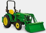
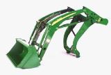
John Deere 3036E Front End Loader
D160 Loader Specifications
Type of Attachment - Front End Loader
Compatibility - JD 3036E
Bucket Width - 1550 mm (61 in.)
Mass - 93 kg (205 lb.)
Hydraulic System Rated Flow - 20 L/min. (5 gpm)
Hydraulic Maximum Pressure - 17202 kPa (172 bar) (2495 psi)
Lift Height (Maximum) To Pivot Pin - 2140 mm (84 in.)
Bucket Level Clearance - 1979 mm (78 in.)
Bucket Dumped Clearance - 1596 mm (63 in.)
Overall Length - 2893 mm (114 in.)
Digging Depth - 131 mm (5 in.)
Reach At Maximum Lift Height with Bucket Dumped - 603 mm (24 in.)
Bucket Reach on Ground with Bucket Leveled - 1369 mm (54 in.)
Dump Bucket Angle - 44°
Dump Bucket Angle at Ground - 122°
Rollback Bucket Angle - 31°
Overall Height In carrying position - 161 mm (6 in.)
Lift Capacity To Maximum Height at Pivot Point - 539 kg (1186 lb.)
Lift Capacity To Maximum Height - 384 kg (845 lb.)
Lift Capacity To 1500 mm (59 in.) at pivot pin - 588 kg (1294 lb.)
Lift Capacity To 1500 mm (59 in.) - 444 kg (977 lb.)
Breakout Force At Pivot Point - 7580 N (1704 lb.-force)
Breakout Force At 500 mm forward of pivot point - 5356 N (1204
lb.-force)
Bucket Rollback Force At maximum height - 6374 N (1433 lb.-force)
Bucket Rollback Force At 1500 mm (59 in) lift height - 8069 N (1814
lb.-force)
Bucket Rollback Force At Ground Level Line - 6325 N (1422 lb.-force)
Loader Raise Time - 3.31 sec.
Loader Lower Time - 2.75 sec.
Bucket Dump Time - 1.75 sec.
Bucket Rollback Time - 1.88 sec.
305 Loader Specifications
Type of Attachment - Front End Loader
Compatibility - JD 3036E
Lifting capacity at pivot pin (maximum height) - 1186 lb. (539 kg)
Lifting capacity at 0.5 m ahead of pivot pin - 845 lb. (389 kg)
Lifting capacity to 59 in. at pivot pin - 1294 lb. (588 kg)
Lifting capacity to 59 in. at 0.5 m ahead - 977 lb. (444 kg)
Maximum Lifting height at pivot pin - 84 in. (2,14 m)
Reach at maximum height - 24 in. (0,61 m)
Breakout force at pivot pin - 1704 lbf. (7579N)
Dump angle - 43,8 degrees
Rollback angle - 31,4 degrees
Loader raising/lowering time - 3,31/2,75 sec.
Bucket dump time/regen - 1,75/1,00 sec.
Bucket rollback time - 1,88 sec.
Check and Adjust Boom Anti-Spill
Limit Switches (305 Loader) - Remove and retain nuts and
washers and outer cover. Cut tie band. Disconnect plugs from connectors
on wiring harness. Remove and retain self-tapping screw. Loosen nuts and
slide switches to end of slots. Rotate cam arm upward until both switch
rollers are centered in cam indentations. Slide each switch until roller
contacts center of cam indentation and tighten nuts. Using a continuity
tester on plugs, confirm switch contacts are OPEN (no continuity) with
cam arm raised. Lower cam arm. Install flange head self-tapping screw
through cam arm and into boom. Using a continuity tester on plugs,
confirm switch contacts are CLOSED with cam arm down. Make sure plugs
are correctly installed in connectors. Install plugs in switch
connectors. Install new tie band around wiring harness. Install cover
and fasten using nuts and washers.
John Deere 3036E Mower Deck
60-Inch Mower Deck Specifications
Model - 60D AutoConnect Mid-Mount Mower
Mower Type - Mulch or Side Discharge
Compatibility - JD 3036E
Cutting Blades - Three
Overall Width - 1900 mm (75.3 in.)
Overall Length - 104 mm (41 in.)
Cutting Height - 38-127 mm (1-1/2 -5 in.)
Cutting Width - 1500 mm (60.9 in.)
Mower Weight - 147 kg (324 lb)
Blade Bolt Torque - 122 Nm (90 lb-ft)
Gearbox Oil Capacity - 136 ml (4.6 oz)
72-Inch Mower Deck Specifications
Model - 72D AutoConnect Mid-Mount Mower
Mower Type - Mulch or Side Discharge
Compatibility - JD 3036E
Cutting Blades - Three
Overall Width - 2190 mm (86 in.)
Overall Length - 1140 mm (45 in.)
Cutting Height - 38-127 mm (1-1/2 -5 in.)
Cutting Width - 1800 mm (72.8 in.)
Mower Weight - 156 kg (345 lb)
Blade Bolt Torque - 122 Nm (90 lb-ft)
Gearbox Oil Capacity - 136 ml (4.6 oz)
Install Mid Rockshaft
- Position rockshaft bushings with flange end facing centerline of John
Deere 3036E tractor, and between half clamp and mid rockshaft. Position
block clamp on top of mid rockshaft and install all parts to tractor
with four M12x90 hex head bolts. Tighten bolts to 130 Nm (96 lb-ft).
Adjusting Mower Level (Side-to-Side)
- Park machine on a level surface, not on a slope. Lock park brake.
Disengage mower blades. Raise 60D mower fully and stop engine. Remove
key. Wait for engine and all moving parts to stop before leaving
operator’s seat. Remove height lock pin. Lower mower slowly to desired
cutting height. Pull height lock link fully forward and lock at first
hole available. Lower mower so pin supports height. Measure distance
from ground to right blade and left blade. Remove retaining ring from
right or left rear link support. Adjust only one link at a time. Adjust
link as necessary to level deck. Install retaining ring.
John Deere 3036E Rotary Cutter
MX5 Rotary Cutter Specifications
Model - MX5 Rotary Cutter
Compatibility - JD 3036E
Cutting Width - 152 cm (60 in.)
Cutting Height - 2,5-24 cm (1-9-1/2 in.)
Overall Width - 162 cm (64 in.)
Overall Length - 260 cm (102 in.)
Body Depth - 21,6 cm (8-1/2 in.)
Upper Deck Thickness - 0,3 cm (1/8 in.)
Lower Deck Thickness - 0,3 cm (1/8 in.)
Total Thickness - 0,6 cm (1/4 in.)
Skirt Thickness - 0,6 cm (1/4 in.)
Horsepower (minimum) - 18.6 kW (25 hp)
Power Take-Off (PTO) - 540 rpm
Hitch Type - Integral Hitch, Category 1
Driveline Size - Category 3
Driveline Protection (Tractor-to-Gear Case) - Self-Adjusting Slip Clutch
Blades Holder - Round Pan (Stump Jumper)
Blades Type - Suction, 1,3x10,2 cm (1/2 x 4 in.)
Blade Tip Speed (540 PTO rpm) - 72.9 m/s (14,347 ft/min)
Brush Cutting Capacity - 5 cm (2 in.)
Weight - 330 kg (728 lb)
Install PTO Driveline (MX5 Rotary
Cutter) - Remove two quick-lock pins and raise PTO
shield. Remove paint from gear case input shaft using a wire brush.
Apply multipurpose grease on input shaft. Pull locking collar toward
slip clutch. Align splines of slip clutch hub with gear case input shaft
and slide hub onto shaft until locking collar snaps into place. Lower
PTO shield and install quick-lock pins. Attach chain at location. Remove
screw and tag.
________________________________________________________________________________
________________________________________________________________________________________
________________________________________________________________________________________
________________________________________________________________________________________
________________________________________________________________________________________
________________________________________________________________________________________
________________________________________________________________________________________
________________________________________________________________________________________
________________________________________________________________________________________
________________________________________________________________________________________
________________________________________________________________________________________
________________________________________________________________________________________
________________________________________________________________________________________
________________________________________________________________________________________
________________________________________________________________________________________
________________________________________________________________________________________
________________________________________________________________________________________
________________________________________________________________________________________
________________________________________________________________________________________
________________________________________________________________________________________
________________________________________________________________________________________
________________________________________________________________________________________
________________________________________________________________________________________
________________________________________________________________________________________
________________________________________________________________________________________
________________________________________________________________________________________
________________________________________________________________________________________
________________________________________________________________________________________
________________________________________________________________________________________
________________________________________________________________________________________
________________________________________________________________________________________
________________________________________________________________________________________
________________________________________________________________________________________
________________________________________________________________________________________
________________________________________________________________________________________
________________________________________________________________________________________
________________________________________________________________________________________
________________________________________________________________________________________
________________________________________________________________________________________
________________________________________________________________________________________
________________________________________________________________________________________
________________________________________________________________________________________
________________________________________________________________________________________
 JD SPECS
 JD LOADERS
 JD MAINTENANCE
 JD INSTRUCTIONS
 JD PROBLEMS
 JD 2025R
 JD 3039R
 JD 4044R
 JD 4105
 JD 4720
 420 Loader
 419 Loader
 510 Loader
 512 Loader
 520 Loader
 520M Loader
 540M NSL
 540 Loader
 440R Loader
 H180 Loader
 JD 5045E
 JD 5085E
 JD 5100M
 JD 6105R
 JD 6120M
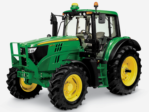 JD 6155M
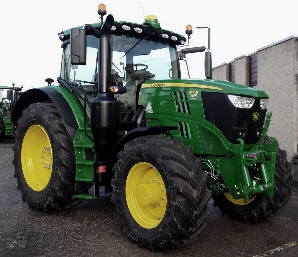 JD 6195R
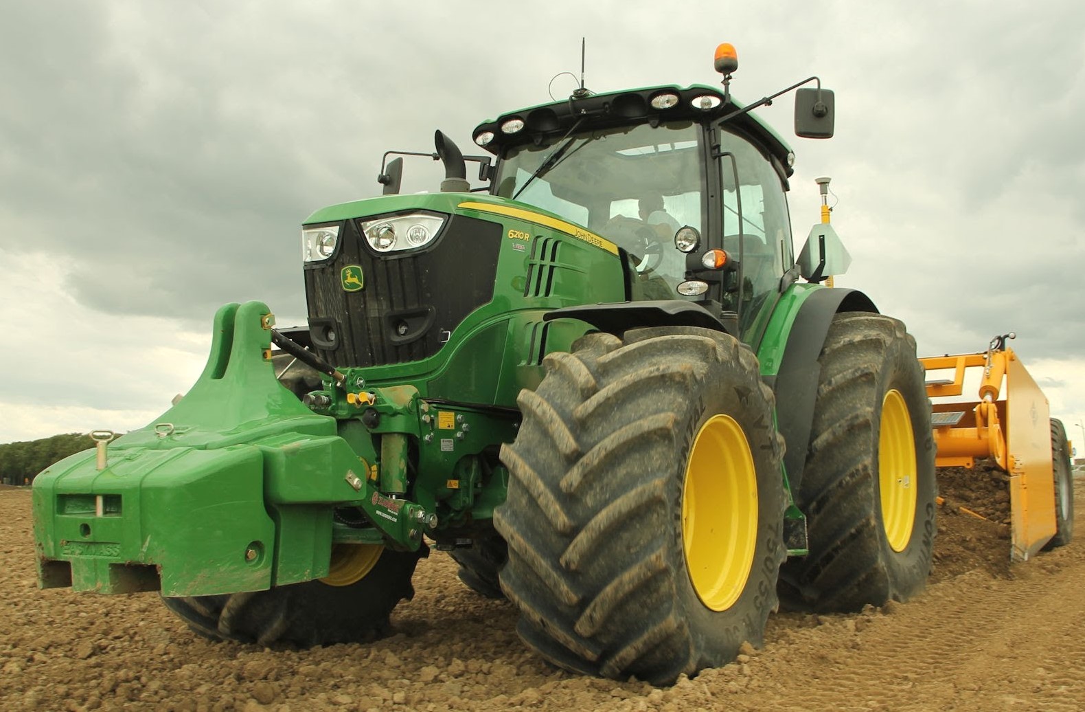 JD 6210R
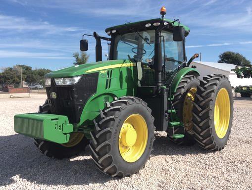 JD 7210R
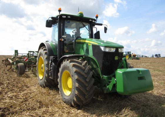 JD 7250R
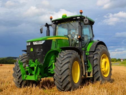 JD 7310R
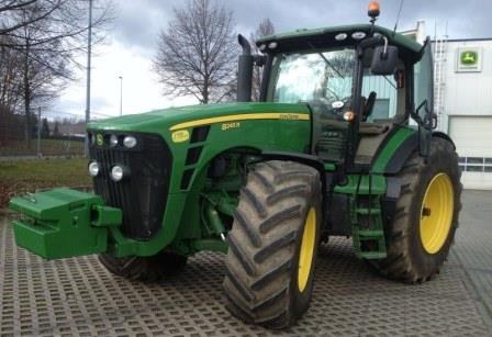 JD 8245R
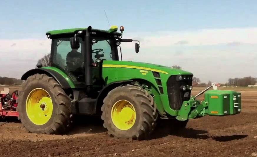 JD 8295R
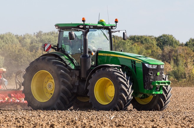 JD 8370R
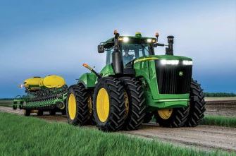 JD 9370R
 120R Loader
 D120 Loader
 H120 Loader
 45 Loader
 200CX Loader
 D160 Loader
 D170 Loader
 H160 Loader
 H165 Loader
 H240 Loader
 210 Loader
 220R Loader
 300E Loader
 300X Loader
 300CX Loader
 JD 9420R
 JD 9510R
 JD GX335
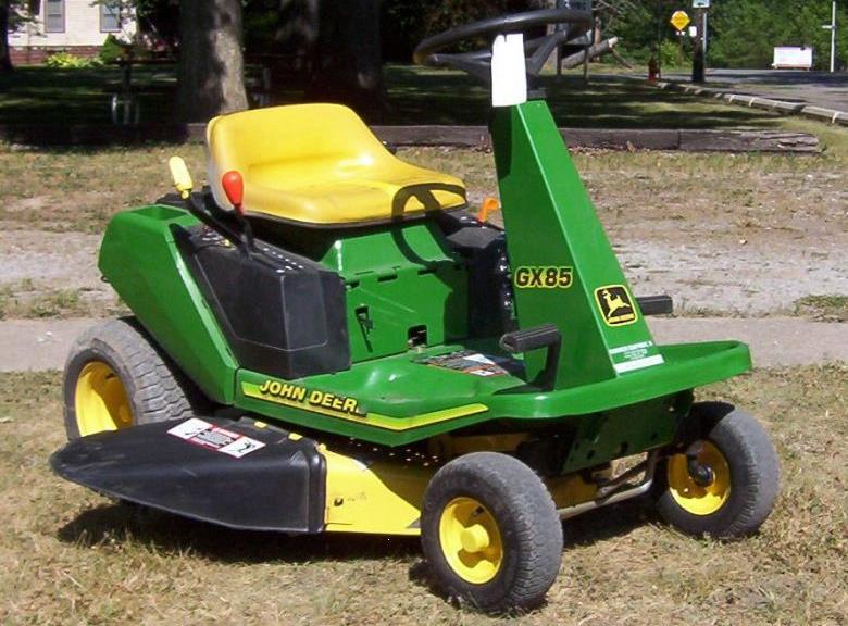 JD GX85
 JD LA105
 JD 5065M
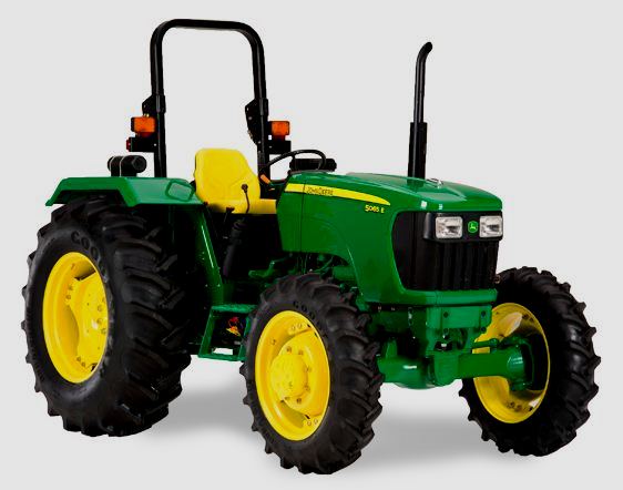 JD 5055D
 JD 5115R
 JD 5105M
 JD 6110R
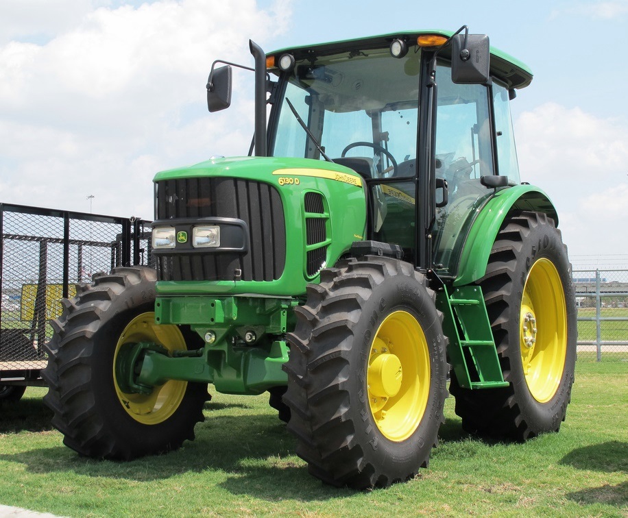 JD 6130D
 JD 6225
 JD 7530
 JD 4044M
 JD 7185J
 300 Loader
 300R Loader
 320R Loader
 400E Loader
 410 Loader
 430 Loader
 460 Loader
 521 Loader
 531 Loader
 541 Loader
 551 Loader
 631 Loader
 651 Loader
 661 Loader
 603R Loader
 JD D130
 JD D160
 JD 325
 JD 335
 JD 345
 JD 2520
 JD 3005
 JD 3720
 JD 1025R
 JD 3033R
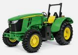 JD 5090EL
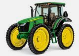 JD 5100MH
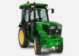 JD 5075GV
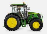 JD 6090RC
 JD 6110B
 623R Loader
 643R Loader
 731 Loader
 746 Loader
 751 Loader
 533 Loader
 583 Loader
 633 Loader
 653 Loader
 683 Loader
 H260 Loader
 663R Loader
 663 Loader
 683R Loader
 753 Loader
 JD 6125J
 JD 6150RH
 JD 6210J
 JD 7195J
 JD 8310
 JD 6325
 JD 5525
 JD 5083EN
 JD 5100GN
 JD 5125R
 210C Backhoe
 300D Backhoe
 310G Backhoe
 410G Backhoe
 710G Backhoe
 80 Loader
 100 Loader
 146 Loader
 148 Loader
 158 Loader
 168 Loader
 175 Loader
 522 Loader
 542 Loader
 540R Loader
 562 Loader
 563 Loader
 673 Loader
 741 Loader
 L108 Automatic
 L120 Automatic
 LA110 Automatic
 LA120 Automatic
 LA150 Automatic
 LT155
LT155 LT160 Automatic
 LT180 Automatic
 LTR180
 X165
X165 E100
E100 E120
E120 E150
E150 LTR166
 LA135
LA135 LA165
LA165 LX277
LX277 LX288
LX288 LX255
LX255 S240
S240 GT235
GT235 G110 Automatic
 JD 3203
 JD 5520
 JD 316
 JD 420
 JD 425
 JD 445
 JD_5050D
 X300
X300 X304
X304 X310
X310 X110 Automatic
 H310 Loader
 H340 Loader
 H360 Loader
 H380 Loader
 H480 Loader
 240 Loader
 245 Loader
 260 Loader
 265 Loader
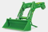 600R Loader
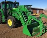 620R Loader
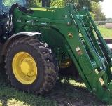 640R Loader
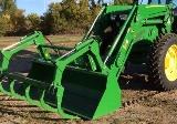 660R Loader
 680R Loader
 JD_5039D
 X146R
X146R X360
X360 X155R
X155R X140 Automatic
 X350
X350 X380
X380 X500
X500 X590
X590 X700
X700 3036E
3036E 2038R
2038R 3038R
3038R 4049M
4049M JD 4100
 X738
X738 X740
X740 X748
X748 X749
X749 X950R
X950R JD 4510
 5045D
5045D 5050E
5050E 5060E
5060E 5078E
5078E