________________________________________________________________________________
John Deere 4410 Attachments
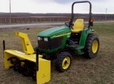
John Deere 4410 Front End Loader
430 Loader Specifications
Type of Attachment - Front End Loader
Compatibility - John Deere 4410
Height (to pin) - 101.4 in. (257 cm)
Clearance, dumped bucket - 78.3 in. (198 cm)
Dump reach - 25.6 in. (65 cm)
Dump angle - 45
Reach at ground - 57.5 in. (146 cm)
Rollback angle - 30
Breakout force (at 800 mm) - 3,299 lb (1496 kg)
Lift to full height (at 800 mm) - 1,259 lb (571 kg)
Raise time to height - 3.5 s
Bucket dump time - 1.8 s
Lowering time - 2.5 s
Rollback time - 2.3 s
Install Bucket/Attachment
- Roll top of attachment back and align hook with holder pin. Using
lifting straps, raise front of loader high enough to allow pin to locate
into holder strap on each side of attachment. Remove quick lock pin from
storage position and install into pin on each side of attachment.
Removing 430 Loader
- Lift up on latch and push forward all the way into notch. Extend lift
cylinders. Masts will lift out of rear frames. Raise masts high enough
to clear front tires. Engage tractor parking brake and/or place
transmission in "Park". Shut off tractor engine and remove key. Move
control lever(s) back and forth and side-to-side several times to
relieve system pressure. Disconnect hoses at couplers and install dust
plugs and caps. Store hoses on lift cylinder, DO NOT lay them on the
ground. Start tractor engine. Disengage tractor parking brake and/or
place transmission in reverse and slowly move away from 430 loader.
Remove ballast box.
300CX Loader Specifications
Type of Attachment - Front End Loader
Compatibility - John Deere 4410
300CX Loader Height (to pin) - 102 in. (2,60 m)
Clearance, dumped bucket - 79,6 in. (2,02 m)
Dump reach - 22 in. (0,55 m)
Dump angle - 41,1
Reach at ground - 58,6 in. (1,48 m)
Rollback at ground - 31
Rollback, raised - 119
Breakout force (at pin) - 3327 lb (1509 kg)
Breakout force (at 0,5 m) - 2416 lb (1095 kg)
Lifting (full height at pin) - 1598 lb (724 kg)
Lifting (full height at 0,5 m) - 1122 lb (508 kg)
Lifting at 1,5 m (at pin) - 2125 lb (963 kg)
Lifting at 1,5 m (at 0,5 m) - 1649 lb (747 kg)
Bucket width - 61 in. (1,54 m)
Attachment style - Deere quick-attach / skid steer (optional)
Raise time to height - 3,6 s.
Bucket dump time - 4,2 s.
Lowering time - 2,1 s.
Rollback time - 1,8 s.
John Deere 4410 Backhoe
447 Backhoe Specifications
Type of Attachment - Backhoe
Compatibility - John Deere 4410
447 Backhoe Transport Height (Max.) - 6 ft. 9 in. (2.1 m)
Bucket Rotation - 180 deg.
Loading Height (Bucket at 60 Deg.) - 6 ft. 6.5 in. (2.0 m)
Digging Depth - 7 ft. 8 in. (2.3 m)
Reach from Center of Swing Pivot - 10 ft. 4 in. (3.1 m)
Swing Arc - 180 deg.
Loading Reach (Bucket at 60 Deg.) - 3 ft. 7 in. (1.1 m)
Ground Clearance - 9.5 in.(241 mm)
SAE Dipperstick Digging Force - 2,005 lb. (8919 N)
SAE Bucket Digging Force - 2,840 lb. (12 633 N)
Boom Lift Capacity @ 36 Inches - 595 lb. (245 Kg)
Backhoe Control Valve Main-Relief Setting - 2,250 psi (15 513 kPa))
Stabilizer Spread, Down (Approx.) - 7 ft. 5 in. (2.2 m)
Stabilizer Spread, Up (Approx.) - 5 ft. 1 in. (1.6 m)
Operating Weight (w/Standard Bucket and Subframe) - 1,077 Ib. (490 kg)
Bucket Options Width - 9,13,16, 20, 24, 36 in. (229, 330, 406, 508, 610,
and 914 mm)
Standard Bucket Width - 9 in. (229 mm)
Bucket Width - 41 cm (16 in.)
SAE Struck Capacity - 0.028 m3 (0.98 ft3)
Heaped Capacity - 0.038 m3 (1.33 ft3)
Bucket Width - 51 cm (20 in.)
SAE Struck Capacity - 0.036 m3 (1.26 ft3)
Heaped Capacity - 0.049 m3 (1.74 ft3)
Install Rockshaft Assist (RSA)
Mounting Plates for 447 Backhoe - Install both mount
weldments in bottom of rear axle with two M16x60 cap screws, spacers,
and 5/8 in. washers. Tighten to 40 Nm (30 lb-ft). Install RSA mounting
plates onto mount weldments from rear of tractor. Avoid pinching
electrical wires. Loosely install two M16x45 cap screws and 5/8 in.
washers in both mount weldments. Loosely install one M16x45 cap screw
and 5/8 in. washer in both RSA mounting plates and hex spacers. Loosely
install four M16x60 cap screws and washers in both RSA mounting plates.
Tighten hardware on both sides in the following order: Tighten the four
M12x55 cap screws and two M12 hex nuts to 95 Nm (70 lb-ft). Tighten the
four M16x45 cap screws installed on the top of the rear axle to 258 Nm
(190 lb-ft). Tighten the four M16x60 cap screws installed on the bottom
of the rear axle to 258 Nm (190 lb-ft). Tighten the eight M16x60 cap
screws installed in the RSA mounting plates to 217 Nm (160 lb-ft).
Tighten the two M16x45 cap screws installed in the threaded hex spacers
to 163 Nm (120 lb-ft). Install fenders if removed. Mount rear wheels in
widest tread width position. Inflate tires to maximum pressure
recommended by tire manufacturer. Install Tall Folding Roll Over
Protection System (ROPS). Install Front Loader. Install Power Beyond
kit. Follow machine operator’s manual instructions to check hydraulic
fluid level.
John Deere 4410 Snowblower and Blade
47-inch Snowblower Specifications
Snowblower Type - Front Mount, Two-stage
Compatibility - JD 4410
Cutting Width - 47 in. (1.2 m)
Overall Cutting Height - 23 in. (584 mm)
Auger Diameter - 16 in. (406 mm)
Rotor Fan Diameter - 16 in. (406 mm)
Chute Rotation - Hydraulic
Drive - Mid PTO
Weight (Approx.) - 400 Ib. (181 kg)
Hydraulic spout rotation - 200 degrees
Worm-gear drive - With durable cast-iron housing
Skid shoes - Three-position skid shoes
Snow-deflector spout - Adjustable
64-inch Snow blower Specifications
Model - Frontier SB1164
Type - Rear Mount
Compatibility - JD 4410
Hitch - Cat. 1 iMatch
Steel skid shoes - Adjustable and replaceable
Cutting edge - Welded
Park Stand - Standard
Chute type - Two part
Chute deflector - Manual standard
Optional deflector adjustment - 3000 psi. (14,647 kPa)
Chute rotation - Manual or hydraulic 245 degrees
Working height - 26 in. (66.0 cm)
Transport width - 64 in. (162.6 cm)
Working width - 64 in. (162.6 cm)
Length - 41 in. (104.1 cm)
Roller chain - #60
Chain idler adjustment - Manual
Chute diameter - 8 in. (20.3 cm)
Auger diameter - 15 in. (38.1 cm)
Auger speed - 170 RPM
Impeller speed - 540 RPM
Impeller blades - 4
Impeller diameter - 24 in. (61.0 cm)
Tractor PTO speed - 540 RPM
Minimum tractor HP - 20 PTO HP
Maximum tractor HP - 50 PTO HP
Auger overload protection - Shearbolt
PTO overload protection - Shearbolt
Operating weight - 531 lb. (240.9 kg)
Shipping weight - 533 lb. (241.8 kg)
Install 64-inch Snow blower with
Quick Hitch - Remove the nut and the lockwasher from the
cat.1 lower hitch pins. Place the jam nut so to obtain 2 1/4" (57mm)
minimum between the edge of the hole of the lower hitch pin and the jam
nut. Insert the lower hitch pins in the upper hole of the hitch and
secure with the lockwasher and the nut. Tighten at 440 ft-lb (597 NM).
Insert a 2 1/8" lg bushing on each pin and lock in place with two 7/16"
linchpins. Insert the 1 7/8" lg bushing between the upper attaching
plates and lock in place with the John Deere 2026R tractor hitch pin and
linchpin.
Install the eyebolt in the upper hole of the left or right side of the
three point hitch by screwing the eyebolt nut to the top and locking
eyebolt in place with a 3/8" serrated flange nut. Make sure the quick
hitch latches are closed. Lower the three point so the quick hitch hooks
are lower than the hitch pins of the snow blower. Move back slowly the
tractor toward the snowblower until hooks are below the hitch pins of
the snowblower. Raise the three point until the quick hitch latches
close on the snowblower hitch pins to lock the system.
60" Rear Blade Specifications
Model - Frontier RB1060L
Type - Rear Mount
Compatibility - JD 4410
Overall Width - 60 inch (152 cm)
Weight (Mass) - 160 lbs. (73 kg)
Moldboard Thickness - 7 Gauge (4.5 mm)
Cutting Edge (Reversible) - 1/2" x 6" (12.7 mm x 152 mm)
Position - 360° Pivot
Offset (Left or Right) - 12 inches (30.5 cm)
Angle (Left or Right) - 15° or 30°
Pitch Adjustment - Controlled by top link
Tractor Rating - Max. Engine 25 hp (18.7 kW)
Tractor 3-Point - Cat 0 or 1
Options Skid Shoe - Cat 1 Quick Hitch Bushing Kit
Implement Code for Tractor Ballast - 9.1
John Deere 4410 Mower
60-inch Mower Deck Specifications
Model - 60" 7-Iron Mid-Mount Mower Deck
Compatibility - JD 4410
Cutting Height - Adjustable, 1.1 to 7.8 in. (27.9 to 198.1 mm) / 1 to
8.75 in. (25 to 222.3 mm)
Overall Width - 72.5 in. (1.84 m)
Blades - 3, heat-treated alloy steel, 2.5x20.5x.312-in. (63.5 x 521 x
7.9 mm) thick
Deck - One-piece stamped steel, .177-in. thick (7 ga.)
Gauge Wheels - Adjustable, greaseable bearings
Gearbox - Spiral gear, John Deere design
Spindles - Greaseable from top
Mower Drive - Mid-PTO to driveshaft on mower
Mower Lift - Steel rod from rear rockshaft; optional mid-rockshaft
cylinder for independent operation of mower
Net Weight - 325 Ib. (147 kg)
Install Hydraulic Cylinder
- Attach rod end of cylinder to lift arm weldment with M12x60 pin, M12
washer and cotter pin. Attach head end of cylinder: Tractor without cab:
Attach head end of cylinder to bracket on bottom of left hand footdeck
support with M12x60 pin and locking ring. Tractor with cab: Attach head
end of cylinder to bracket with M12x60 pin and locking ring. Route
cylinder hoses up through the opening next to the left side ROPS.
Connect cylinder base end hose to top Third SCV outlet. Connect cylinder
rod end hose to bottom Third SCV outlet. Tie hoses to hydraulic line
about 15 cm (6 in.) behind bracket. Install more ties to secure hoses as
needed.
Install Adjustable Depth Rod
- Install knob retainer on left draft support with two M8x25 bolts, two
M9 washers and two M8 nuts. Install depth stop on left draft support.
Install threaded end of adjustable depth rod through depth stop. Install
14 mm x 25 mm bushing on threaded end of rod. Attach other end of
adjustable depth rod to lift arm weldment with M12x60 pin, M12 washer
and locking ring. You may need to adjust the knob to attach adjustable
yokes to the mower. Install knob and thread it 4-5 turns onto the depth
rod.
72-inch Mower Deck Specifications
Model - 72" 7-Iron Mid-Mount Mower Deck
Compatibility - JD 4410
Width of Cut - 72.8 in. (1849 mm)
Width - 85 in. (2159 mm)
Length - 41.7 in. (1060 mm)
Height - 17.1 in. (435 mm)
Minimum Cutting Height - 1 in. (25 mm)
Blades - 3
Gauge Wheels - Polyolefin
Spindles - 1.00 in. (25.4 mm)
Net Weight - 331 Ib. (150 kg)
Installing 72" Mower Deck
- Slide Mower Under Machine: Remove quick lock pin, and disconnect
spring assembly from both front wheel shafts to allow wheels to turn
freely. Install quick lock pins in both front wheel shafts. Remove
locking ring and drilled pin from both rear wheel shafts. Turn rear
wheels sideways. Install drilled pins and locking rings. Turn machine
steering wheel fully left. Slide mower from right side of machine into
position under lift system. Install Driveline - Pull collar back and
install driveline onto machine mid-PTO shaft. Push driveline onto PTO
shaft until it snaps into locked position. Push and pull driveline to be
sure collar is locked.
Adjusting Upstop Clearance
- Check to be sure rear upstop is positioned in top hole for 72-inch
mower installation on Mid Chassis tractor. Adjust mower level
front-to-rear. Adjust mower level side-to-side. With mower in raised
position, measure front upstop clearance. Adjust yokes as necessary to
provide 3 mm (1/8 in.) front upstop clearance with mower in raised
position.
John Deere 4410 Rotary Broom
60 Inch Rotary Broom Specifications
Compatibility - JD 4410
Overall Broom Height - 77 cm (30.5 in)
Overall Broom Width - 1.6 m (62 in)
Sweeping width when angled 0° - 1.5 m (57 in)
Sweeping width when angled 30° left or right - 1.3 m (50 in)
Brush Diameter - 66 cm (26 in)
Brush Material - Polypropylene and Steel
Sections - 32
Angling - 0-30° Each Side
Angling Method - Hydraulic
Speed - 200 rpm
Caster Wheels - 160 x 80 mm (6-1/4 x 3-1/4 in.)
Brush Drive - Front PTO
Broom Gearbox Reduction - 3 to 1, Straight Bevel Gear, Shear Pin
Protected
Final Drive - Chain and sprocket, core sprocket taper lock hub
Weight - 203 kg 448 lb
Remove Brush Core -
Lower 60 Inch Rotary Broom to 76 mm (3 in.) off the ground. Support
brush head in raised position with wood blocks or a safe lifting device.
Remove six screws and chain guard from right side of broom. Locate
master link retaining clip on drive chain. Remove master link to
disconnect chain. Remove chain from large sprocket. Loosen two set
screws on each bearing lock collar at ends of brush core. Remove snap
ring at large sprocket. Remove set screws.
Install one of the removed set screws into threaded hole. Turn set screw
at hole clockwise until locking hub, sprocket, square key, and set screw
can be removed from brush core. Remove hex nuts, lock washers, and
carriage bolts to remove right park stand assembly. Loosen two nuts at
left end of brush core. Slide brush core toward left end of 60" broom
housing. Remove three nuts, lock washers, and carriage bolts securing
right end of bearing and flanges in position. Pull brush core from broom
housing. Remove two flanges and end bearing from right end of brush
core.
________________________________________________________________________________
________________________________________________________________________________________
________________________________________________________________________________________
________________________________________________________________________________________
________________________________________________________________________________________
________________________________________________________________________________________
________________________________________________________________________________________
________________________________________________________________________________________
________________________________________________________________________________________
________________________________________________________________________________________
________________________________________________________________________________________
________________________________________________________________________________________
________________________________________________________________________________________
________________________________________________________________________________________
________________________________________________________________________________________
________________________________________________________________________________________
________________________________________________________________________________________
________________________________________________________________________________________
________________________________________________________________________________________
________________________________________________________________________________________
________________________________________________________________________________________
________________________________________________________________________________________
________________________________________________________________________________________
________________________________________________________________________________________
________________________________________________________________________________________
________________________________________________________________________________________
________________________________________________________________________________________
________________________________________________________________________________________
________________________________________________________________________________________
________________________________________________________________________________________
________________________________________________________________________________________
________________________________________________________________________________________
________________________________________________________________________________________
________________________________________________________________________________________
________________________________________________________________________________________
________________________________________________________________________________________
________________________________________________________________________________________
________________________________________________________________________________________
________________________________________________________________________________________
________________________________________________________________________________________
________________________________________________________________________________________
________________________________________________________________________________________
________________________________________________________________________________________
 JD SPECS
 JD LOADERS
 JD MAINTENANCE
 JD INSTRUCTIONS
 JD PROBLEMS
 JD 2025R
 JD 3039R
 JD 4044R
 JD 4105
 JD 4720
 420 Loader
 419 Loader
 510 Loader
 512 Loader
 520 Loader
 520M Loader
 540M NSL
 540 Loader
 440R Loader
 H180 Loader
 JD 5045E
 JD 5085E
 JD 5100M
 JD 6105R
 JD 6120M
 JD 6155M
 JD 6195R
 JD 6210R
 JD 7210R
 JD 7250R
 JD 7310R
 JD 8245R
 JD 8295R
 JD 8370R
 JD 9370R
 120R Loader
 D120 Loader
 H120 Loader
 45 Loader
 200CX Loader
 D160 Loader
 D170 Loader
 H160 Loader
 H165 Loader
 H240 Loader
 210 Loader
 220R Loader
 300E Loader
 300X Loader
 300CX Loader
 JD 9420R
 JD 9510R
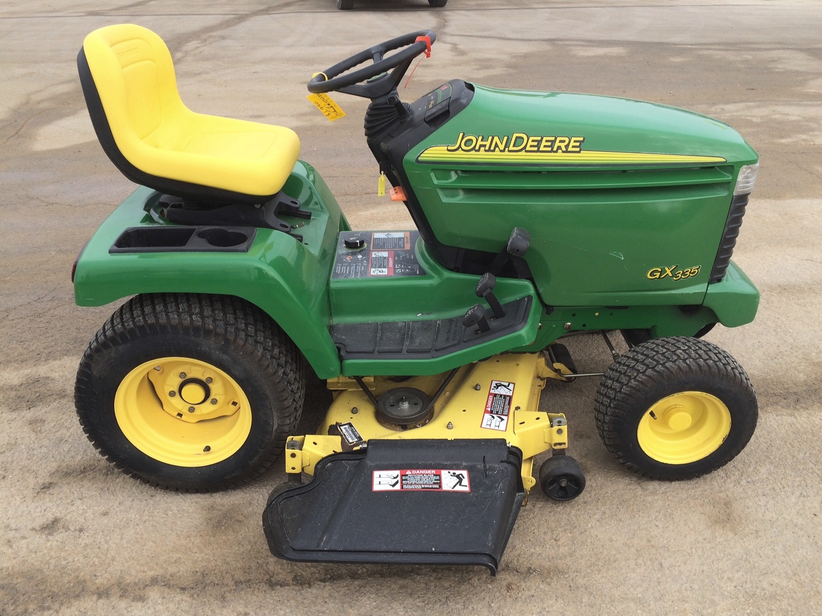 JD GX335
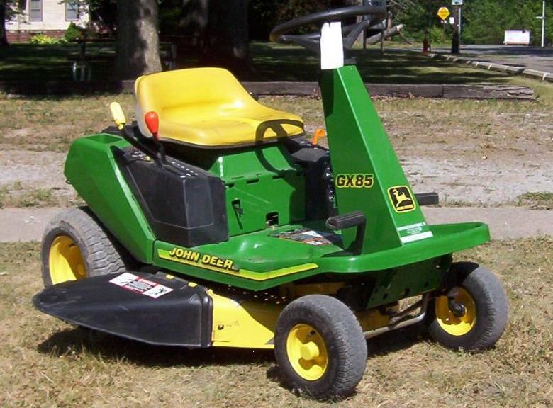 JD GX85
 JD LA105
 JD 5065M
 JD 5055D
 JD 5115R
 JD 5105M
 JD 6110R
 JD 6130D
 JD 6225
 JD 7530
 JD 4044M
 JD 7185J
 300 Loader
 300R Loader
 320R Loader
 400E Loader
 410 Loader
 430 Loader
 460 Loader
 521 Loader
 531 Loader
 541 Loader
 551 Loader
 631 Loader
 651 Loader
 661 Loader
 603R Loader
 JD D130
 JD D160
 JD 325
 JD 335
 JD 345
 JD 2520
 JD 3005
 JD 3720
 JD 1025R
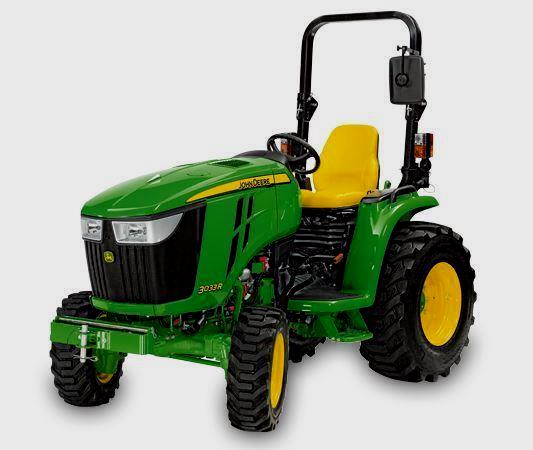 JD 3033R
 JD 5090EL
 JD 5100MH
 JD 5075GV
 JD 6090RC
 JD 6110B
 623R Loader
 643R Loader
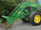 731 Loader
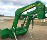 746 Loader
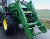 751 Loader
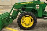 533 Loader
 583 Loader
 633 Loader
 653 Loader
 683 Loader
 H260 Loader
 663R Loader
 663 Loader
 683R Loader
 753 Loader
 JD 6125J
 JD 6150RH
 JD 6210J
 JD 7195J
 JD 8310
 JD 6325
 JD 5525
 JD 5083EN
 JD 5100GN
 JD 5125R
 210C Backhoe
 300D Backhoe
 310G Backhoe
 410G Backhoe
 710G Backhoe
 80 Loader
 100 Loader
 146 Loader
 148 Loader
 158 Loader
 168 Loader
 175 Loader
 522 Loader
 542 Loader
 540R Loader
 562 Loader
 563 Loader
 673 Loader
 741 Loader
 L108 Automatic
 L120 Automatic
 LA110 Automatic
 LA120 Automatic
 LA150 Automatic
 LT155
LT155 LT160 Automatic
 LT180 Automatic
 LTR180
 X165
X165 E100
E100 E120
E120 E150
E150 LTR166
 LA135
LA135 LA165
LA165 LX277
LX277 LX288
LX288 LX255
LX255 S240
S240 GT235
GT235 G110 Automatic
 JD 3203
 JD 5520
 JD 316
 JD 420
 JD 425
 JD 445
 JD_5050D
 X300
X300 X304
X304 X310
X310 X110 Automatic
 H310 Loader
 H340 Loader
 H360 Loader
 H380 Loader
 H480 Loader
 240 Loader
 245 Loader
 260 Loader
 265 Loader
 600R Loader
 620R Loader
 640R Loader
 660R Loader
 680R Loader
 JD_5039D
 X146R
X146R X360
X360 X155R
X155R X140 Automatic
 X350
X350 X380
X380 X500
X500 X590
X590 X700
X700 3036E
3036E 2038R
2038R 3038R
3038R 4049M
4049M JD 4100
 X738
X738 X740
X740 X748
X748 X749
X749 X950R
X950R JD 4510
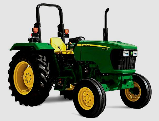 5045D
5045D 5050E
5050E 5060E
5060E 5078E
5078E