________________________________________________________________________________
John Deere 6068 diesel - Cylinder head inspect and reassembly operations
Remove cylinder head
Remove rocker arm cover, if not previously done. Drain all engine oil
and coolant. Disconnect turbocharger oil inlet line at turbocharger or
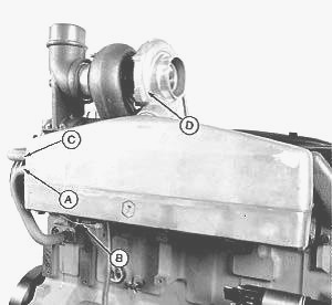
oil conditioning housing. Remove water manifold (A) and all coolant
piping. Remove turbocharger (B) and exhaust elbow (E). Remove air intake
manifold (C). Remove exhaust manifold.
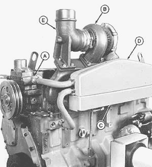
A—Water Manifold, B—Turbocharger, C—Intake Manifold, D—Aftercooler
Assembly, E—Exhaust Elbow
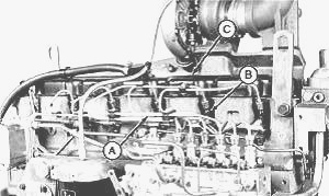
Remove fuel injection lines (A) and nozzles (B). Remove rocker arm cover
(C) and ventilator outlet hose assembly.
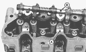
Remove six cap screws (A) and remove all four clamps (B). Lift rocker
arm assembly up and remove. Remove wear caps from valve stems. Remove
all 12 push rods and identify for reassembly.

Clean and inspect push rods as explained later in this group. Remove all
26 cylinder head cap screws. If cylinder head gasket failed, check and
record each cylinder head cap screw torque before removing. Make a
reference mark (in-line) on socket and cylinder head surface. Loosen cap
screw at least 1/2 turn. Retighten cap screw (using torque wrench) until
reference marks align, and record torque.
Remove cylinder head gasket. Inspect possible oil, coolant, or
combustion chamber leaks. Also, check for evidence of incorrect or
defective head gasket being used. Do not rotate crankshaft with cylinder
head removed unless all cylinder liners are secured with cap screws and
large flat washers as described later in this group.
Disassemble and inspect rocker arm shaft assembly
Make preliminary inspection during disassembly. Look for: Worn or scored
rocker arms, shaft, and shaft support. Weak or broken springs. Lube oil
restriction. Remove plugs and washers from ends of rocker arm shaft.
Slide springs, rocker arms, and rocker arm supports off rocker arm shaft
identifying their parts for reassembly in the same sequence they were in
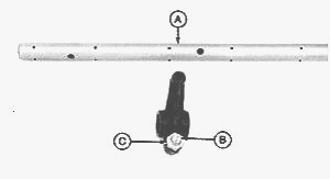
before disassembly. Inspect rocker arm shaft (A) for severe scratching,
scoring, or excessive wear at points of rocker arm contact. Measure
rocker arm and shaft. Compare with specifications given below.
Wear could indicate weak valve springs, bent push rods, or loose rocker
arm shaft clamps.
ROCKER ARM ASSEMBLY SPECIFICATIONS
Rocker Arm I.D - 19.07—19.10 mm (0.7507—0.7520 in.)
Rocker Arm Shaft O.D - 19.01—19.05 mm (0.7484—0.7500 in.)
Check rocker arm adjusting nut (C) and screw (B) for damage. Visually
inspect rocker arm for hairline cracks. Replace if necessary. Be sure
all oil holes in rocker arm shaft are clean and open. Clean all rocker
arm parts with clean solvent. Dry with compressed air. Check for cups or
concave wear on ends of rocker arms where they contact wear caps.
Examine spacer springs on shaft between rocker arms. Be sure they are
strong enough to exert a positive pressure on rocker arms. If the rocker
arm has been damaged by a valve failure, replace it and the push rods
when replacing valves. Roll rocker arm shaft and push rods on a flat
surface to check for bends or distortion. Replace parts as necessary.
Assemble and inspect rocker arm shaft assembly - Assemble parts on
rocker arm shaft opposite removal procedure. Make sure rocker arm shaft
end plugs are firmly seated against end of shaft, and washers are
installed on shaft.
Inspect and clean cylinder head
Inspect all John Deere 6068 diesel cylinder head passages for
restrictions. Heads with restricted or clogged passages can be cleaned
by soaking them in a tank of hot caustic solution. Scrape all old gasket
material from head. Use a powered wire brush to clean sealing surfaces.
If cylinder head is not put in a chemical hot tank for cleaning, clean
with solvent and a brush. Dry with compressed air and be sure to blow
out all passages.
Check cylinder head combustion face flatness - Check cylinder head
flatness using D05012ST Precision Straightedge and feeler gauge. Check
lengthwise, crosswise, and diagonally in several places. If any
measurement exceeds this specification, the cylinder head must be either
resurfaced or replaced.
CYLINDER HEAD TOP DECK FLATNESS SPECIFICATION
Maximum Out-of-Flat (Over Entire Length or Width) - 0.102 mm (0.0040
in.)
Straightness per any 305 mm (12 in.) Length - 0.025 mm (0.001 in.)
Measure cylinder head Thickness - Measure head thickness from valve
cover gasket rail-to-combustion face. If cylinder head thickness is less
than wear limit. Do not attempt to resurface. Install a new cylinder
head. If necessary to resurface cylinder head, a maximum of 0.762 mm
(0.030 in.) can be ground from new part dimension. Remove only what is
necessary to restore flatness. After resurfacing, check flatness as
described earlier and check surface finish on combustion face of head.
Check valve recess after grinding. Valve seat or valve face may be
ground to bring this characteristic within specification.
CYLINDER HEAD SPECIFICATIONS
Thickness - 155.45—155.71 mm (6.120—6.130 in.)
Wear Limit - 154.69 mm (6.09 in.)
Combustion Face Surface Finish (AA) - 0.015—0.0028 mm (60—110 micro-in.)
Maximum Wave Depth - 0.008 mm (0.0003 in.)
Install cylinder head
Thoroughly inspect new cylinder head gasket for possible manufacturing
imperfections. Return any gasket that does not pass inspection. Be sure
cylinder head and block gasket surfaces are clean, dry, and free of any
oil. Put a new head gasket on JD 6068 diesel cylinder block. Do not use
sealant on gasket; install dry. If cylinder head is lowered onto
cylinder block and you discover that the head is not positioned
correctly on locating dowels, remove cylinder head and install a new
gasket. Do not try to reposition cylinder head on the same gasket again
since the fire ring will possibly be damaged. Lower cylinder head everly
to correct position on block using appropriate lifting equipment. Make
sure that head is positioned correctly over dowels.
Install rocker arm assembly - Install push rods (A) in holes from which
removed. Install wear caps (B) on valves, making certain caps rotate
freely. Make sure spring pin (A) engages with hole (B) in shaft. Install
shaft clamps (B) and all six cap screws (A). Tighten cap screws to 75 Nm
(55 lb-ft).

Complete final assembly of injection pump side - Adjust valve clearance
as directed earlier in this group. Apply Adhesive or equivalent to new
gasket, and seal gasket to rocker arm cover (B). Be sure to follow the
manufacturer’s directions on the package for correct application
procedures and curing times. Install cover and tighten cap screws to 8
Nm (6 lb-ft) (72 lb-in.). Install fuel injection nozzles (E), leak-off
lines (D) and fuel injection lines (C). Connect ventilator outlet hose
to adapter on rocker arm cover and tighten clamp securely. Install water
manifold.
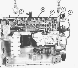
A—Water Manifold, B—Rocker Arm Cover, C—Fuel Injection Lines, D—Leak-off
Lines, E—Fuel Injection Nozzles
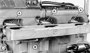
Complete final assembly on exhaust manifold side - Install front exhaust
manifold using new gaskets. Do not tighten cap screws until sealing ring
and rear exhaust manifold is installed. Install rear exhaust manifold
using new gaskets and sealing ring. Tighten cap screws in sequence shown
in bottom illustration to 47 Nm (35 lb-ft). Install turbocharger oil
return pipe, using a new O-ring.
On some John Deere Engines, using new gaskets install intake manifold
(A). Tighten cap screws to 47 Nm (35 lb ft). On some Engines, install
intake coupling (B). Do not tighten clamps. On some Engines, install
turbocharger (C), adapter (D), and exhaust elbow (E). Position intake
adapter with turbocharger and intake manifold and tighten clamps
securely.
A—Intake Manifold, B—Intake Coupling, C—Turbocharger, D—Turbocharger
Adapter, E—Exhaust Elbow
On JD diesel, use new gaskets (A) and install intake manifold (B).
Tighten cap screws to 47 Nm (35 lb-ft).
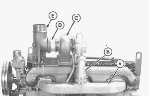
On JD Engines, using new gaskets and O-rings, install aftercooler and
cover - Install water inlet (A) and water outlet (C) hoses. Tighten hose
clamps securely. Install aneroid line (B), if equipped, and tighten
securely. Install turbocharger (D) with couplings. Tighten cap screws to
47 Nm (35 lb-ft). If engine oil was drained from crankcase, install new
oil filter and fill with clean oil of correct grade and viscosity. Fill
cooling system with clean coolant. Perform engine break-in.
A—Water Inlet Hose, B—Aneroid Line, C—Water Outlet Tube and Hose,
D—Turbocharger
Perform engine break-in - Run John Deere 6068 diesel engine at slow idle
no load for 2 minutes. Check for liquid leaks. Increase RPM to fast
idle, then load down to 50 rpm above rated speed for 20 minutes.
Dynamometer is the preferred load control, but engine can be loaded by
matching drag loads to gear selection. Recheck valve clearance and
adjust as necessary. Install rocker arm cover gasket and cover. Tighten
rocker arm cover cap screws to 8 Nm (6 lb-ft) (72 lb-in.). Retorque of
cylinder head cap screws after engine break-in is not required.
________________________________________________________________________________
________________________________________________________________________________________
 JD SPECS
 JD LOADERS
 JD MAINTENANCE
 JD INSTRUCTIONS
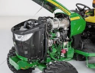 JD PROBLEMS
________________________________________________________________________________________
 JD 2025R
 JD 3039R
 JD 4044R
 JD 4105
 JD 4720
________________________________________________________________________________________
 420 Loader
 419 Loader
 510 Loader
 512 Loader
 520 Loader
________________________________________________________________________________________
 520M Loader
 540M NSL
 540 Loader
 440R Loader
 H180 Loader
________________________________________________________________________________________
________________________________________________________________________________________
 JD 5045E
 JD 5085E
 JD 5100M
 JD 6105R
 JD 6120M
________________________________________________________________________________________
 JD 6155M
 JD 6195R
 JD 6210R
 JD 7210R
 JD 7250R
________________________________________________________________________________________
 JD 7310R
 JD 8245R
 JD 8295R
 JD 8370R
 JD 9370R
________________________________________________________________________________________
 120R Loader
 D120 Loader
 H120 Loader
 45 Loader
 200CX Loader
________________________________________________________________________________________
 D160 Loader
 D170 Loader
 H160 Loader
 H165 Loader
 H240 Loader
________________________________________________________________________________________
 210 Loader
 220R Loader
 300E Loader
 300X Loader
 300CX Loader
________________________________________________________________________________________
 JD 9420R
 JD 9510R
 JD GX335
 JD GX85
 JD LA105
________________________________________________________________________________________
 JD 5065M
 JD 5055D
 JD 5115R
 JD 5105M
 JD 6110R
________________________________________________________________________________________
 JD 6130D
 JD 6225
 JD 7530
 JD 4044M
 JD 7185J
________________________________________________________________________________________
 300 Loader
 300R Loader
 320R Loader
 400E Loader
 410 Loader
________________________________________________________________________________________
 430 Loader
 460 Loader
 521 Loader
 531 Loader
 541 Loader
________________________________________________________________________________________
 551 Loader
 631 Loader
 651 Loader
 661 Loader
 603R Loader
________________________________________________________________________________________
 JD D130
 JD D160
 JD 325
 JD 335
 JD 345
________________________________________________________________________________________
 JD 2520
 JD 3005
 JD 3720
 JD 1025R
 JD 3033R
________________________________________________________________________________________
 JD 5090EL
 JD 5100MH
 JD 5075GV
 JD 6090RC
 JD 6110B
________________________________________________________________________________________
 623R Loader
 643R Loader
 731 Loader
 746 Loader
 751 Loader
________________________________________________________________________________________
 533 Loader
 583 Loader
 633 Loader
 653 Loader
 683 Loader
________________________________________________________________________________________
 H260 Loader
 663R Loader
 663 Loader
 683R Loader
 753 Loader
________________________________________________________________________________________
 JD 6125J
 JD 6150RH
 JD 6210J
 JD 7195J
 JD 8310
________________________________________________________________________________________
 JD 6325
 JD 5525
 JD 5083EN
 JD 5100GN
 JD 5125R
________________________________________________________________________________________
 210C Backhoe
 300D Backhoe
 310G Backhoe
 410G Backhoe
 710G Backhoe
________________________________________________________________________________________
 80 Loader
 100 Loader
 146 Loader
 148 Loader
 158 Loader
________________________________________________________________________________________
 168 Loader
 175 Loader
 522 Loader
 542 Loader
 540R Loader
________________________________________________________________________________________
 562 Loader
 563 Loader
 673 Loader
 741 Loader
________________________________________________________________________________________
 L108 Automatic
 L120 Automatic
 LA110 Automatic
 LA120 Automatic
 LA150 Automatic
________________________________________________________________________________________
 LT155
LT155 LT160 Automatic
 LT180 Automatic
 LTR180
 X165
X165________________________________________________________________________________________
 E100
E100 E120
E120 E150
E150 LTR166
________________________________________________________________________________________
 LA135
LA135 LA165
LA165 LX277
LX277 LX288
LX288 LX255
LX255________________________________________________________________________________________
 S240
S240 GT235
GT235 G110 Automatic
 JD 3203
 JD 5520
________________________________________________________________________________________
 JD 316
 JD 420
 JD 425
 JD 445
________________________________________________________________________________________
 JD_5050D
 X300
X300 X304
X304 X310
X310 X110 Automatic
________________________________________________________________________________________
 H310 Loader
 H340 Loader
 H360 Loader
 H380 Loader
 H480 Loader
________________________________________________________________________________________
 240 Loader
 245 Loader
 260 Loader
 265 Loader
 280 Loader
________________________________________________________________________________________
 600R Loader
 620R Loader
 640R Loader
 660R Loader
 680R Loader
________________________________________________________________________________________
 JD_5039D
 X146R
X146R X360
X360 X155R
X155R X140 Automatic
________________________________________________________________________________________
 X350
X350 X380
X380 X500
X500 X590
X590 X700
X700________________________________________________________________________________________
 3036E
3036E 2038R
2038R 3038R
3038R 4049M
4049M JD 4100
________________________________________________________________________________________
 X738
X738 X740
X740 X748
X748 X749
X749 X950R
X950R________________________________________________________________________________________
 JD 4510
 5045D
5045D 5050E
5050E 5060E
5060E 5078E
5078E