________________________________________________________________________________
John Deere AG150/AG250 transmission - Repairing the range clutch shaft
- All gear range clutch trains are dismantled in the same way.
- All the gear trains possess a clutch.
The Massey Ferguson 8270, 8210, 8260 tractor
gear range clutch trains are identified as follows:
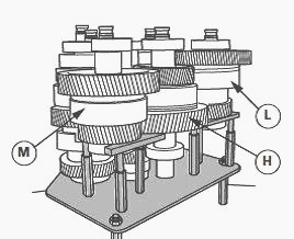
Fig.61
"L" clutch - 5th stage shaft
"H" clutch - 6th stage shaft
"M" clutch - 7th stage shaft
Take care that the shaft is properly supported to avoid toppling and
damage to the pinions.
- Install a suitable split bearing extractor (OEM 4175 or equivalent) on
the first bearing. The split bearing extractor must be placed in such a
manner that its flat surface is turned towards the pinion. Tighten the
extractor bolts until the bearing begins to extract from the 7th stage
shaft.
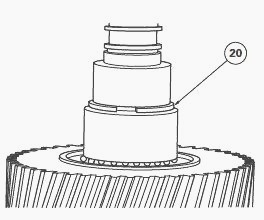
Fig.62
- Hook the pinion extractor beneath the split bearing extractor and
remove the bearing from the shaft by pulling. Remove the circlips (20)
from the shaft.
- Place the pinion extractor sleeve (ATP 3030) on the pinion and tighten
the bolts. To be able to extract the pinion from the shaft, the
extractor sleeve must be tightened around the external diameter of the
pinion. In certain cases, use of the main sleeve is specified and must
be fitted beneath the pinion. Hook the pinion extractor beneath the
extractor sleeve and remove the pinion and bearingfrom the shaft by
pulling upwards.
- Take off circlip (12) and closing plate (11), the thrust plates,
clutch discs and clutch housing.
- Place a suitable pinion extractor on the internal pinion bearing (13)
and remove it from the shaft.
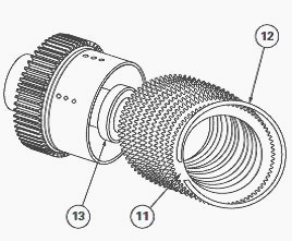
Fig.63
- Place the clutch train in a press. Place tool ATP 3002 on the
Belleville washers. Compress the washers, remove circlip and release the
pressure on the washers.
- Remove the MF 8270, 8210, 8260 tractor clutch train from the press and
take off the holding washer of circlip (9) and Belleville washers (8)
from the clutch.
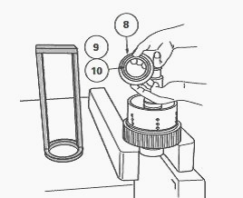
Fig.64
- Remove the oil seal washer located between the Belleville washers (8)
and the clutch piston.
- Once all the Belleville washers are removed, feed compressed air into
the clutch pressurized oil channel, near shaft seal ring. This will
eject the piston from the clutch housing.
- Disassemble the opposite end of the shaft in the same manner. The best
method of supporting the shaft is to have a 76 mm diameter hole in the
workbench to receive the shaft.
- Compress the Belleville washers and remove the circlip using tool ATP
3002.
- Take off the washing retaining the circlip, the Belleville washers and
the oil seal washer.
- Remove the clutch piston.
5th stage shaft
Massey Ferguson 8260, 8210, 8270 tractor AG
150 transmission (fig.65)
(1) 5th stage pinion shaft - 74 teeth (2) "L" clutch linings - 10 thrust
plates and discs (3) Pinion "L" clutch hub - 40 teeth. Use extractor
sleeves ATP 3030-1 and ATP 3030-10 to remove the pinion. (4) Clutch
piston (5) External piston seal - type "D" bush seal (6) Internal piston
seal - O’ring (7) Oil seal washer (8) Belleville washers (9) Circlip
retaining washer (10) Circlip (11) Closing plate (12) Clutch lining
circlip (13) Protected ball bearing of "L"clutch internal pinion hub
(14) Ball bearing of "L" clutch external pinion hub (15) Clutch
lubricating oil regulation O’ring (16) Forward shaft ball bearing (17)
Rear shaft roller bearing (18) Circlip (19) Circlip (22) "L" clutch
pressurized oil channel (23) Pressurized oil channel (24) Lubricating
port
Instructions
(13) The protected ball bearing must be installed with the protective
device facing the clutch linings.
(17) The roller bearing must be installed with the bearing circlip
facing the centre of the shaft
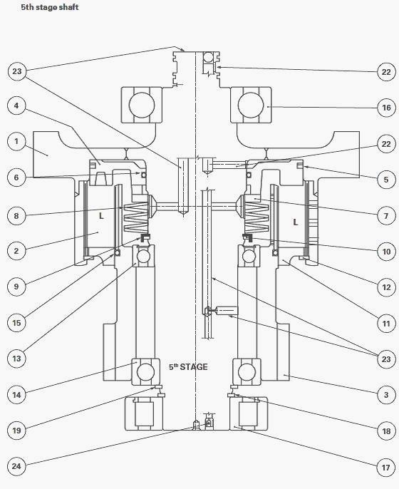
Fig.65. 5th stage shaft
MF 8260, 8210, 8270 tractor AG 250
transmission
(1) 5th stage pinion shaft - 80 teeth (2) "L" clutch linings - 10 thrust
plates and discs (3) Pinion "L" clutch hub - 44 teeth. Use extractor
sleeves ATP 3030-1 and ATP 3030-12 to remove the pinion. (4) Clutch
piston (5) External piston seal - type "D" bush seal (6) Internal piston
seal - O’ring (7) Oil seal washer (8) Belleville washers (9) Circlip
retaining washer (10) Circlip (11) Closing plate (12) Clutch lining
circlip (13) Protected ball bearing of "L" clutch internal pinion hub
(14) Ball bearing of "L" clutch external pinion hub (15) Clutch
lubricating oil regulation O’ring (16) Forward shaft ball bearing -
hardened bearing (17) Rear shaft roller bearing (18) Circlip (19)
Circlip (22) "L" clutch pressurized oil channel (23) Pressurized oil
channel (24) Lubricating port
Instructions
(13) The protected ball bearing must be installed with the protective
device facing the clutch linings.
(16) The SH2 bearing must be installed here. The SH2 bearing is a
hardened bearing providing twice the normal life span.
(17) The roller bearing must be installed with the bearing circlip
facing the centre of the shaft
6th stage shaft
John Deere AG 150 transmission (Fig.66)
(1) 6th stage pinion shaft - 72 teeth (2) "H" clutch linings - 10 thrust
plates and discs (3) Pinion - "H" clutch hub - 48 teeth. Use extractor
sleeves ATP 3030-1 and ATP 3030-155 to remove the pinion. (4) Clutch
piston (5) External piston seal - type "D" bush seal (6) Internal piston
seal - O’ring (7) Oil seal washer (8) Belleville washers (9) Circlip
retaining washer (10) Circlip (11) Closing plate (12) Clutch lining
circlip (13) Protected ball bearing of "H" clutch internal pinion hub
(14) Ball bearing of "H" clutch external pinion hub (15) Clutch
lubricating oil regulation O’ring (16) Forward shaft ball bearing (17)
Rear shaft roller bearing (20) Circlip (21) Distance piece sleeve (22)
"H" clutch pressurized oil channel (23) Pressurized oil channel (24)
Lubricating port
Instructions
(13) The protected ball bearing must be installed with the protective
device facing the clutch linings.
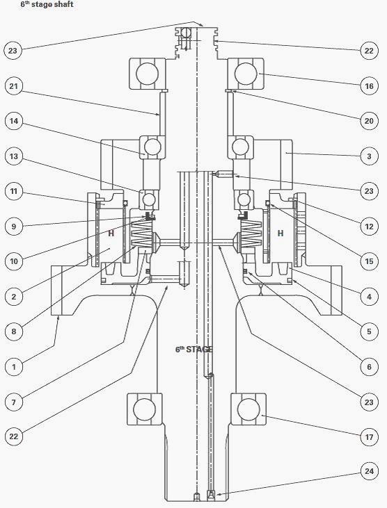
Fig.66. 6th stage shaft
John Deere AG 250 transmission
(1) 5th stage pinion shaft - 81 teeth (2) "H" clutch linings - 10 thrust
plates and discs (3) Pinion "H" clutch hub - 53 teeth. Use extractor
sleeves ATP 3030-1 and ATP 3030-16 to remove the pinion. (4) Clutch
piston (5) External piston seal - type "D" bush seal (6) Internal piston
seal - O’ring (7) Oil seal washer (8) Belleville washers (9) Circlip
retaining washer (10) Circlip (11) Closing plate (12) Clutch lining
circlip (13) Protected ball bearing of "H" clutch internal pinion hub
(14) Ball bearing of "H" clutch external pinion hub (15) Clutch
lubricating oil regulation O’ring (16) Forward shaft ball bearing -
hardened bearing (17) Rear shaft roller bearing - hardened bearing (20)
Circlip (21) Distance piece sleeve (22) "H" clutch pressurized oil
channel (23) Pressurized oil channel (24) Lubricating port
Instructions
(13) The protected ball bearing must be installed with the protective
device facing the clutch linings.
(16) The SH2 bearing must be installed here. The SH2 bearing is a
hardened bearing providing twice the normal life span.
(17) The SH2 bearing must be installed here. The SH2 bearing is a
hardened bearing providing twice the normal life span.
7th stage shaft
Massey Ferguson 8210, 8270, 8260 tractor AG
150 transmission (Fig.67)
(1) 7th stage pinion shaft - 65 teeth (2) "M" clutch linings - 10 thrust
plates and discs (3) Pinion "M" clutch hub - 40 teeth. Use extractor
sleeves ATP 3030-1 and ATP 3030-10 to remove the pinion. (4) Clutch
piston (5) External piston seal - type "D" bush seal (6) Internal piston
seal - O’ring (7) Oil seal washer (8) Belleville washers (9) Circlip
retaining washer (10) Circlip (11) Closing plate (12) Clutch lining
circlip (13) Protected ball bearing of "M" clutch internal pinion hub
(14) Ball bearing of "M" clutch external pinion hub (15) Clutch
lubricating oil regulation O’ring (16) Forward shaft ball bearing (17)
Rear shaft roller bearing (18) Circlip (22) "M" clutch pressurized oil
channel (23) Pressurized oil channel (24) Lubricating port
Instructions
(13) The protected ball bearing must be installed with the protective
device facing the clutch linings.
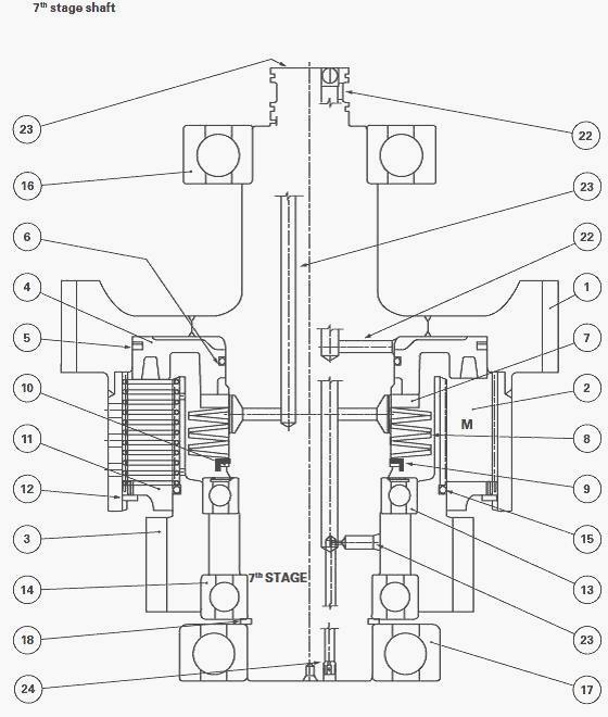
Fig.67. 7th stage shaft
MF 8270, 8210, 8260 tractor AG 250
transmission
(1) 7th stage pinion shaft - 75 teeth (2) "M" clutch linings - 10 thrust
plates and discs (3) Pinion "M" clutch hub - 47 teeth. Use extractor
sleeves ATP 3030-1 and ATP 3030-13 to remove the pinion. (4) Clutch
piston (5) External piston seal - type "D" bush seal (6) Internal piston
seal - O’ring (7) Oil seal washer (8) Belleville washers (9) Circlip
retaining washer (10) Circlip (11) Closing plate (12) Clutch lining
circlip (13) Protected ball bearing of "M" clutch internal pinion hub
(14) Ball bearing of "M" clutch external pinion hub (15) Clutch
lubricating oil regulation O’ring (16) Forward shaft ball bearing -
hardened bearing (17) Rear shaft roller bearing - hardened bearing (18)
Circlip (22) "M" clutch pressurized oil channel (23) Pressurized oil
channel (24) Lubricating port
Instructions
(13) The protected ball bearing must be installed with the protective
device facing the clutch linings.
(16) The SH2 bearing must be installed here. The SH2 bearing is a
hardened bearing providing twice the normal lifetime
(17) The SH2 bearing must be installed here. The SH2 bearing is a
hardened bearing providing twice the normal lifetime
Assembling Massey Ferguson 8270, 8210,
8260 tractor range clutches
- Place the clutch train vertically on the workbench. Install the
internal and external seals on the piston (4). Smear the piston seals
and clutch-housing bore with transmission oil. Fit piston (4) with the
reinforcements and depressions facing outside.
- Install an oil seal washer (7). All the clutch oil seal washers of the
range are identical.
- Install a Belleville washer (8). The first washer closest to the
piston must touch the internal rim of the washer. The second Belleville
washer must touch the external rim of the first washer. Alternate
Belleville washers until they are all installed.
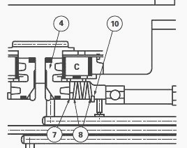
Fig.68
(4) Piston, (7) Oil seal washer, (8) Belleville washers, (10) Circlip
- Place the clutch train in a press. Using tool ATP 3002, compress the
Belleville washers and fit retaining washer and a circlip (10).
- Lubricate the thrust plates and discs with transmission oil as they
are installed. Begin with the thrust plate closest to the piston and
alternate until the 10 thrust plates and 10 friction disks are
installed. Place the splined clutch closing plate on the outside and fit
circlip.
Measuring piston travel
- Using slide callipers fitted with a depth gauge, measure distance A
from the piston to the edge of the clutch housing.
- Inject 4.8 bar compressed air in the oil channel to compress the
Belleville washers. Measure distance B from the piston to the edge of
the clutch housing.
- The difference between these two measurements, A - B equals the piston
travel.
Piston travel
- The piston travel can be adjusted by selecting or exchanging thrust
plates since their thickness varies.
- With new clutch discs and thrust plates - Piston travel: 1.3 to 3.8 mm
- With used clutch discs and thrust plates - Piston travel: 1.8 to 5.5
mm
Reassembling Massey Ferguson 8270,
8210, 8260 tractor clutch range bearings
Certain bearings used in the clutches and on the shafts are directional
and must be installed in the correct direction.
- Push bearing (13) the closest to the clutch linings, on to the shaft
using a compression tool (ATP 3020). Install the bearing with the
protective device facing the clutch lining.
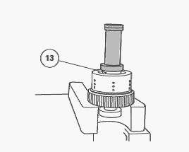
Fig.69
- Install the oil regulation o’ring (15) on clutch hub and lubricate the
o’ring.
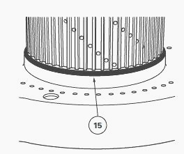
Fig.70
- Install the pinion with the clutch hub (3) in the discs and thrust
plates, over the bearing. The pinion being placed above the bearing.
Turn the pinion and shake lightly so that all the splines of the discs
and thrust plates are correctly engaged and so that the bearing thrusts
against the bottom of the pinion bore.
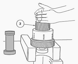
Fig.71
When fitting the hub, ensure that the oil regulation O’ring (15) is not
pinched when it passes the closing plate. The O’ring must be positioned
so that it is loose on the clutch hub.
- Install external pinion hub bearing (14) on the shaft using a
compression tool (ATP 3020) and push it into the pinion hub. Install a
circlip on the shaft of the fifth or seventh stage, or a sleeve and a
circlip on the sixth stage shaft.
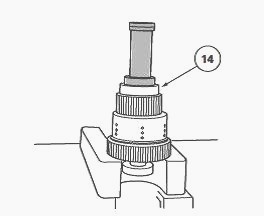
Fig.72
- Place an extraction sleeve (ATP 3030) on the pinion, pull the pinion
and the bearing upwards against the circlip to avoid any lateral load on
the bearings. The hub of the pinion must move longitudinally.
- Place the bearings on the shaft and push them home using a compression
tool (ATP 3020). Bearing of the fifth stage clutch train is a roller
bearing and must be installed so that the bearing circlip faces the
clutch.
- Repeat the procedure at each end of the shaft and for all the speed
clutch shafts.
________________________________________________________________________________
 JD SPECS
 JD LOADERS
 JD MAINTENANCE
 JD INSTRUCTIONS
 JD PROBLEMS
________________________________________________________________________________________
 JD 2025R
 JD 3039R
 JD 4044R
 JD 4105
 JD 4720
________________________________________________________________________________________
 420 Loader
 419 Loader
 510 Loader
 512 Loader
 520 Loader
________________________________________________________________________________________
_______________________________________________________________________________________
 520M Loader
 540M NSL
 540 Loader
 440R Loader
 H180 Loader
________________________________________________________________________________________
 JD 5045E
 JD 5085E
 JD 5100M
 JD 6105R
 JD 6120M
________________________________________________________________________________________
 JD 6155M
 JD 6195R
 JD 6210R
 JD 7210R
 JD 7250R
________________________________________________________________________________________
 JD 7310R
 JD 8245R
 JD 8295R
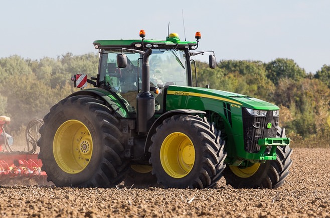 JD 8370R
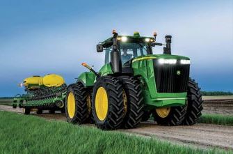 JD 9370R
________________________________________________________________________________________
 120R Loader
 D120 Loader
 H120 Loader
 45 Loader
 200CX Loader
________________________________________________________________________________________
 D160 Loader
 D170 Loader
 H160 Loader
 H165 Loader
 H240 Loader
________________________________________________________________________________________
 210 Loader
 220R Loader
 300E Loader
 300X Loader
 300CX Loader
________________________________________________________________________________________
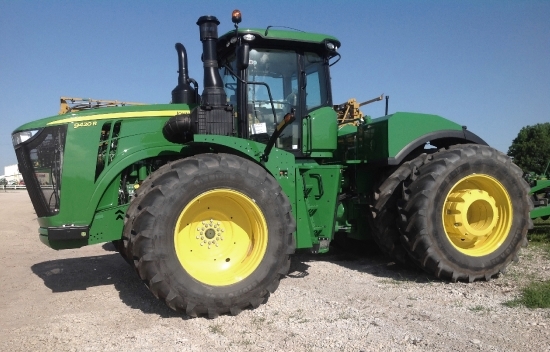 JD 9420R
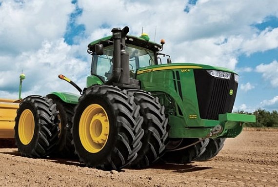 JD 9510R
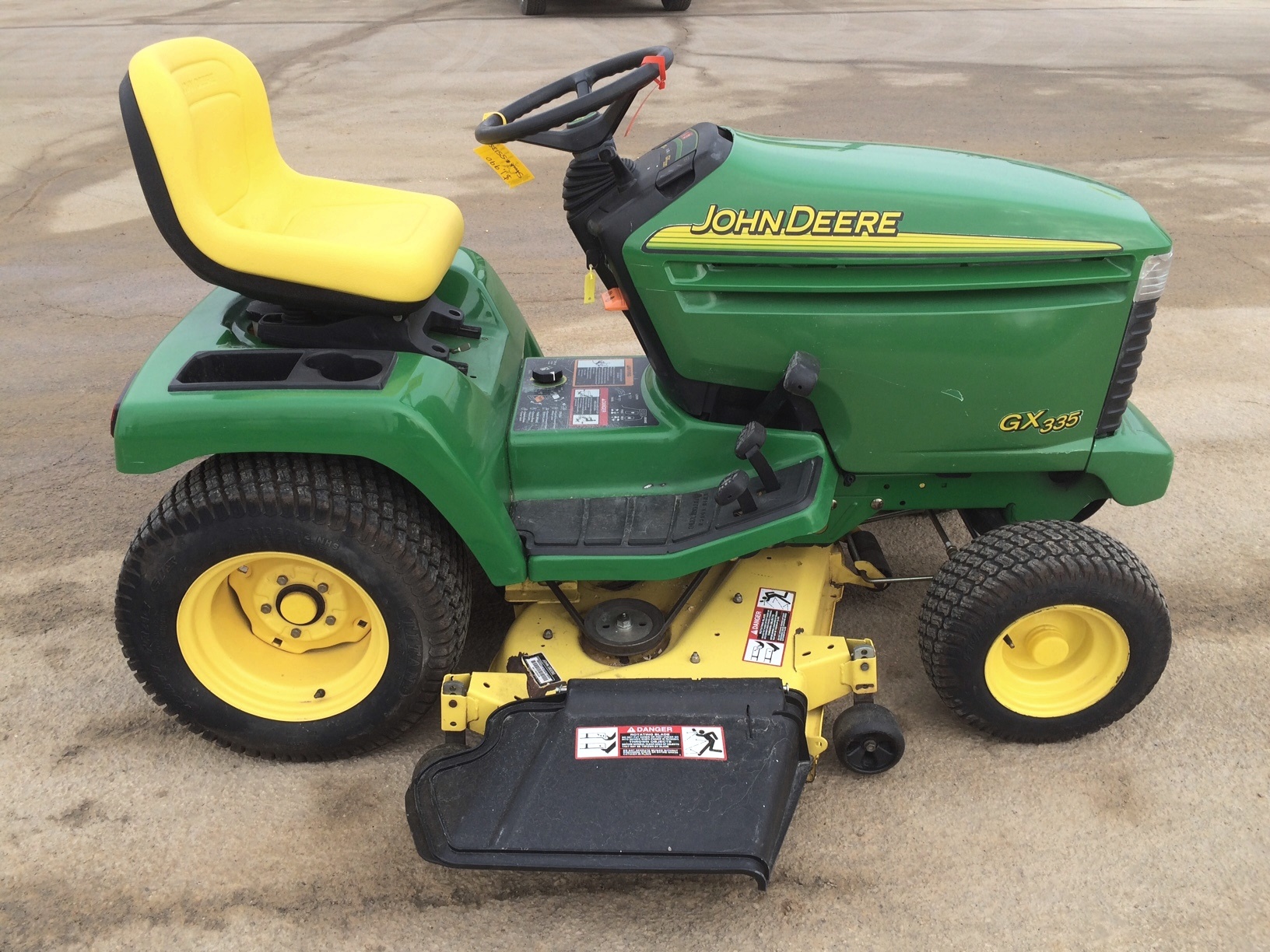 JD GX335
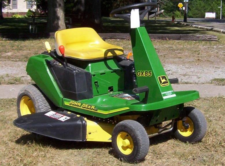 JD GX85
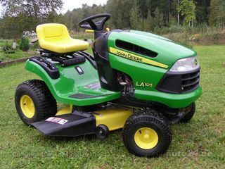 JD LA105
________________________________________________________________________________________
 JD 5065M
 JD 5055D
 JD 5115R
 JD 5105M
 JD 6110R
________________________________________________________________________________________
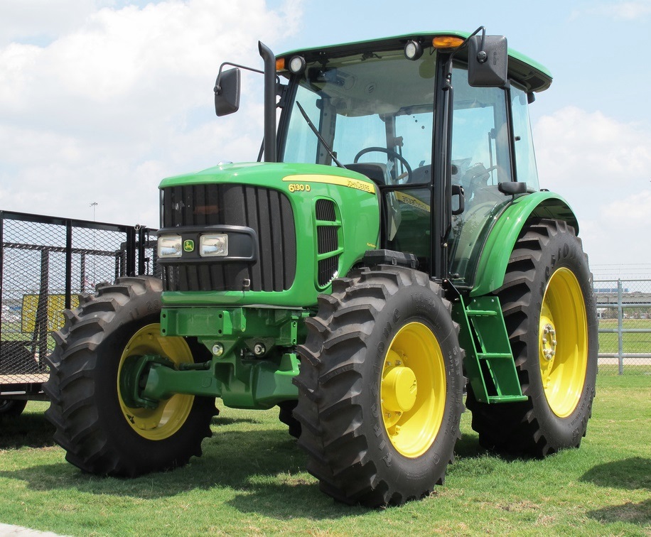 JD 6130D
 JD 6225
 JD 7530
 JD 4044M
 JD 7185J
________________________________________________________________________________________
 300 Loader
 300R Loader
 320R Loader
 400E Loader
 410 Loader
________________________________________________________________________________________
 430 Loader
 460 Loader
 521 Loader
 531 Loader
 541 Loader
________________________________________________________________________________________
 551 Loader
 631 Loader
 651 Loader
 661 Loader
 603R Loader
________________________________________________________________________________________
 JD D130
 JD D160
 JD 325
 JD 335
 JD 345
________________________________________________________________________________________
 JD 2520
 JD 3005
 JD 3720
 JD 1025R
 JD 3033R
________________________________________________________________________________________
 JD 5090EL
 JD 5100MH
 JD 5075GV
 JD 6090RC
 JD 6110B
________________________________________________________________________________________
 623R Loader
 643R Loader
 731 Loader
 746 Loader
 751 Loader
________________________________________________________________________________________
 533 Loader
 583 Loader
 633 Loader
 653 Loader
 683 Loader
________________________________________________________________________________________
 H260 Loader
 663R Loader
 663 Loader
 683R Loader
 753 Loader
________________________________________________________________________________________
 JD 6125J
 JD 6150RH
 JD 6210J
 JD 7195J
 JD 8310
________________________________________________________________________________________
 JD 6325
 JD 5525
 JD 5083EN
 JD 5100GN
 JD 5125R
________________________________________________________________________________________
 210C Backhoe
 300D Backhoe
 310G Backhoe
 410G Backhoe
 710G Backhoe
________________________________________________________________________________________
 80 Loader
 100 Loader
 146 Loader
 148 Loader
 158 Loader
________________________________________________________________________________________
 168 Loader
 175 Loader
 522 Loader
 542 Loader
 540R Loader
________________________________________________________________________________________
 562 Loader
 563 Loader
 673 Loader
 741 Loader
________________________________________________________________________________________
 L108 Automatic
 L120 Automatic
 LA110 Automatic
 LA120 Automatic
 LA150 Automatic
________________________________________________________________________________________
 LT155
 LT160 Automatic
 LT180 Automatic
 LTR180
 X165
________________________________________________________________________________________
 E100
 E120
 E150
 LTR166
________________________________________________________________________________________
 LA135
 LA165
 LX277
 LX288
 LX255
________________________________________________________________________________________
 S240
 GT235
 G110 Automatic
 JD 3203
 JD 5520
________________________________________________________________________________________
 JD 316
 JD 420
 JD 425
 JD 445
________________________________________________________________________________________
 JD_5050D
 X300
 X304
 X310
 X110 Automatic
________________________________________________________________________________________
 H310 Loader
 H340 Loader
 H360 Loader
 H380 Loader
 H480 Loader
________________________________________________________________________________________
 240 Loader
 245 Loader
 260 Loader
 265 Loader
 280 Loader
________________________________________________________________________________________
 600R Loader
 620R Loader
 640R Loader
 660R Loader
 680R Loader
________________________________________________________________________________________
 JD_5039D
 X146R
 X360
 X155R
 X140 Automatic
________________________________________________________________________________________
 X350
 X380
 X500
 X590
 X700
________________________________________________________________________________________
 3036E
 2038R
 3038R
 4049M
 JD 4100
________________________________________________________________________________________
 X738
 X740
 X748
 X749
 X950R
________________________________________________________________________________________
 JD 4510
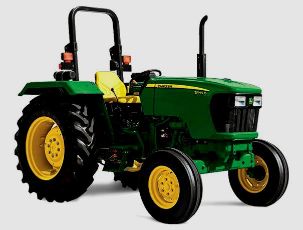 5045D
 5050E
 5060E
 5078E