________________________________________________________________________________
Massey Ferguson 3050, 3060, 3080, 3125 PTO - Intermediate shaft, Driving pinion, Power-take-off brake
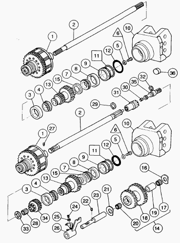
The drive from the engine is transmitted to the power take-off clutch
mounted at the front of the center housing. The intermediate shaft (2)
is connected by splines at one end to the clutch and at the other end
either to the double pinion (13) in the 2-speed PTO version or to the
coupler (31) in the 4-speed economy PTO version. The compound pinion
(13) turns on two taper roller bearings (3) (4) and (7) (8), mounted in
the bore of the center housing and the top link support (10)
respectively. A piston housed in the 3rd point support and controlled by
the 17 bar hydraulic circuit enables the compound pinion (13) to be
braked when the control lever is moved to the PTO braking position.
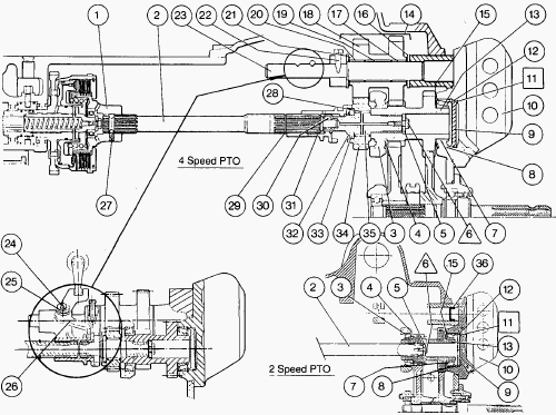
Parts List - (1) Clutch, (2) Intermediate shaft, (3)
Bearing cup, (4) Bearing cone, (5) Washer, (6) Bolt, (7) Bearing cone,
(8) Bearing cup, (9) Brake piston, (10) Top link support, (11) Shims,
(12) O-ring, (13) Driving pinion, (14) Compound pinion assembly, (15)
Deflector, (16) Washer, (17) Needle roller bearing, (18) Compound
pinion, (19) Spacer, (20) Needle roller bearing, (21) Washer, (22) Set
screw, (23) Shaft, (24) Locking screw, (25) Nut, (26) Fork, (27) Screw,
(28) Needle roller bearing, (29) Circlip, (30) Ring, (31) Dog tooth
coupler, (32) Circlip, (33) Washer, (34) Dog tooth pinion, (35) Shaft,
(36) Cup plug
MF 3050, 3060, 3080, 3125 PTO Operation
2-speed PTO
When the PTO solenoid valve feeds the clutch, the intermediate shaft (2)
is driven. This in turn drives the compound driving pinion (13) which
engages constantly with the 540 rpm and 1000 rpm pinions of the lower
line.
4-speed PTO
This feature enables speeds of 540 rpm or 1000 rpm to be obtained with
an engine speed of 1550 rpm. Standard position (engine speed 2000 rpm) -
When the coupler (31) is moved forwards, the intermediate shaft (2)
turns with the shaft (35) which drives the compound driving pinion (13).
This configuration is identical to the 2-speed PTO version. Economy
position (engine speed 1550 rpm) - When the coupler (31) is moved
backwards, the drive is transmitted to the coupler (34) (fitted loose on
the Shaft (35)) and to the compound pinion (18) which drives the driving
pinion (13). The ratio of the Compound pinion (18) is 1.292.
Power-take-off brake
The movement of the control lever in the cab acts on an electrical
contactor which enables the solenoid valve of the PTO brake mounted on
the right cover to open. Oil is supplied to the chamber situated behind
the piston (9). The piston moves and presses the bearing cup (8) against
the bearing cone (7), progressively immobilizing the driving pinion (13)
which constantly engages with the 540 and 1000 rpm pinions.
Massey Ferguson 3050, 3060, 3080, 3125 -
2-speed PTO
Disassembly
Disconnect: auxiliary spool valve supply hose; supply hose of the lift
valve; return hose. Remove the bolts of the auxiliary spool valve
support. Detach the auxiliary spool valve support. Tilt the support and
auxiliary spool valve assembly without detaching the control cables.
Disconnect the supply tube of the PTO brake. Disconnect the lubrication
tube. Remove the bolts and the top link support. Withdraw the pinion and
shaft assembly held by the washer and screw. Remove the bearing cone.
The shaft (2) is mounted in the clutch (1) without locking screw.
Reassembly
Check and clean the parts. Replace those which are defective. Refit the
bearing cone. Fit the pinion (13) and shaft (2) assembly held by the
washer (5) and screw. Clean the joint face of the top link support.
Smear the joint face of the housing with a sealing compound (Loctite 510
or equivalent). To ensure the lubrication of the bearing cone, a cup
plug (36) is fitted without Loctite, recessed into the face of the
housing.
Refit the top link support. Fit and tighten the bolts to a torque of 130-170 Nm. Ensure that the cup is present. Reconnect the supply tube of the PTO brake and the lubrication tube. Clean the joint face of the spool valve support. Smear the joint face of the support cover with a sealing compound (Loctite 510 or equivalent). Refit the support, tilting it. with the control cables.
Smear the threads of the
two lower bolts with Loctite 510. Fit and tighten the bolts to a torque
of 50-70 Nm. Reconnect: spool valve supply hose; supply hose of the lift
valve; return hose. Check the operation of the PTO and its brake. Check
for leaks at the joint faces (spool valve support, top link support); at
the hydraulic connectors.
Massey Ferguson 3050, 3060, 3080, 3125 - 4-speed economy PTO
Disassembly
Remove the left side cover. If removing the screw (27) and the
intermediate shaft (2). Disconnect: spool valve supply hose; supply hose
of the lift valve; return hose. Remove the support. Tilt the support and
spool valve assembly without detaching the cables. Disconnect the
lubrication tube. Remove the bolts of the top link support and detach
it. Remove the nut and the locking screw of the fork. Remove the screw
(22).
Withdraw the shaft (23) from the compound pinion assembly (14) in order to disengage the fork (26). To disengage the fork atone, gently putt the shaft (23) towards the rear. Remove the friction washers (16) and (21). Take care not to drop the washers in the housing. Withdraw the compound pinion assembly (14) (through the aperture of the spool valve support for version without shimming only).
Remove the needle roller bearings (17) and (20) and the spacer (19) of the pinion (18). Remove the circlip (32). Use short-handled pliers to facilitate access to the circlip. Withdraw the pinion (13) and shaft (35) assembly held by the washer (5) and bolt. Remove the flat washer (33). Take care not to drop the circlip and the washer in the housing. Hold the pinion (34) and the needle roller bearing (28).
The bearing cone (4) remains in the cup (3)
during removal of the pinion (13). Remove the pinion (34) and the needle
roller bearing (28). Remove the bearing cone (4). Remove the hexagon
socket setscrew (27) (if necessary). Withdraw the shaft (2) and the
coupler (31) (if necessary). The circlip (29) remains on the shaft (2).
Reassembly
Clean and check the parts. Replace those which are defective. Refit the
shaft (2) and the coupler (31) (if removed). Smear the screw (27) with
Loctite 221 and tighten (if removed). Refit the bearing cone. Advance
the pinion (13) prepared with the shaft (35). Fit the coupler (34), the
needle roller bearing (28), the washer (33) and the circlip. Push on to
the pinion (13). Position the washer (33). Fit the circlip (32).
In the pinion (18), place the spacer (19) and the needle roller bearings (17) and (20). Position the compound pinion assembly (14). Fit the washer (16) smeared with miscible grease (Amber Technical or equivalent). Lightly engage the shaft (23) to hold the washer (16) in place. Fit the washer (21) smeared with miscible grease. Centre the compound pinion assembly (14).
Mount the shaft (23) finally in the pinion assembly (14)
and in the fork (26), ensuring that the hole of the screw (22) is
properly positioned. Smear the screw (22) with Loctite 542. Fit and
tighten to a torque of 28-43 Nm. Clean the joint face of the top link
support. Smear the joint face of the housing with a sealing compound
(Loctite 510 or equivalent). Ensure that the cup is present. Fit and
tighten the bolts to a torque of 130-170 Nm. Reconnect the tubes. Refit
the screw (24) and the nut (25) on the fork (26).
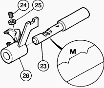
Adjustment of locking of fork (26): Position the fork (26) and the
locking screw (24) on the flat part M of the shaft (23) (between the two
locking notches). Tighten the screw as far as it will go so as to
compress the ball. Loosen the screw by 1/4 of a turn. Smear the nut (25)
with Loctite 241. Tighten to a torque of 15-20 Nm. Check that the fork
is locked correctly. Adjust the control. Clean the joint face of the
spool valve support.
Smear the joint face of the support with a sealing compound (Loctite 510 or equivalent). Refit the support, tilting it, with the control cables. Smear the threads of the two lower bolts with Loctite 510. Tighten the four screws to a torque of 50-70 Nm. Reconnect the hoses. If the screw and intermediate shaft (2) have been removed, refit the left side cover. Check the operation of the PTO and its brake. Check for leaks at the joint faces (spool valve support, top link support, left side cover), at the hydraulic connectors.
________________________________________________________________________________
________________________________________________________________________________
 SPECS
SPECS LOADERS
 MAINTENANCE
 PROBLEMS
________________________________________________________________________________________
| MF TRACTORS SPECIFICATIONS |
 130
130 133
133 145
145 155
155 158
158________________________________________________________________________________________
 165
165 175
175 185
185 188
188 230
230________________________________________________________________________________________
 254
254 254S
254S 284S
284S 294
294 353
353________________________________________________________________________________________
 290
290 362
362 375
375 390
390 398
398________________________________________________________________________________________
 399
399 590
590 690
690 1010
1010 1030
1030________________________________________________________________________________________
 1020
1020 1150
1150 2620
2620 2640
2640 2645
2645________________________________________________________________________________________
 1540
1540 1736
1736 2660
2660 3065
3065 3095
3095________________________________________________________________________________________
 3650
3650 3680
3680 4255
4255 4355
4355 4370
4370________________________________________________________________________________________
 3630
3630 3635
3635 4245
4245 4445
4445 4609
4609________________________________________________________________________________________
 4710
4710 5435
5435 5475
5475 5610
5610 5711
5711________________________________________________________________________________________
 6150
6150 6170
6170 6180
6180 6270
6270 6290
6290________________________________________________________________________________________
 6445
6445 6499
6499 6614
6614 6713
6713 7465
7465________________________________________________________________________________________
 7495
7495 7614
7614 7622
7622 7715
7715 7726
7726________________________________________________________________________________________
 8210
8210 8270
8270 8650
8650 8727
8727 GC1705
________________________________________________________________________________________
| MF FRONT END LOADERS |
 1464 Loader
 1466 Loader
 1040 Loader
 1070 Loader
 905 Loader
________________________________________________________________________________________
 906 Loader
 915 Loader
 916 Loader
 921 Loader
 926 Loader
________________________________________________________________________________________
 931 Loader
 933 Loader
 936 Loader
 938 Loader
 939 Loader
________________________________________________________________________________________
 940 Loader
 941 Loader
 945 Loader
 946 Loader
 948 Loader
________________________________________________________________________________________
 949 Loader
 950 Loader
 951 Loader
 955 Loader
 956 Loader
________________________________________________________________________________________
 958 Loader
 960 Loader
 961 Loader
 965 Loader
 966 Loader
________________________________________________________________________________________
 968 Loader
 975 Loader
 976 Loader
 978 Loader
 985 Loader
________________________________________________________________________________________
 FL.3114 X
 FL.3419 X
 FL.3522
 FL.3615
 FL.3619
________________________________________________________________________________________
 FL.3817
 FL.3819
 FL.3823
 FL.4018
 FL.4121
 916X Loader
 921X Loader
 926X Loader
 931X Loader
 936X Loader
________________________________________________________________________________________
 941X Loader
 946X Loader
 951X Loader
 956X Loader
 988 Loader
________________________________________________________________________________________
 FL.4125
 FL.4227
 FL.4124
 FL.4220
 FL.4323
________________________________________________________________________________________
 FL.4327
 FL.4621
 FL.4624
 FL.4628
 FL.5033
________________________________________________________________________________________
 DL95 Loader
 DL100 Loader
 DL120 Loader
 DL125 Loader
 DL130 Loader
________________________________________________________________________________________
 DL135 Loader
 DL250 Loader
 DL260 Loader
 L90 Loader
 L100 Loader
________________________________________________________________________________________
 L105E Loader
 L210 Loader
 1014 Loader
 1016 Loader
 1462 Loader
________________________________________________________________________________________
 1525 Loader
 1530 Loader
 232 Loader
 838 Loader
 848 Loader
________________________________________________________________________________________
 246 Loader
 1036 Loader
 1038 Loader
 1080 Loader
 856 Loader
________________________________________________________________________________________
| MF TRACTORS MAINTENANCE |
 1010
1010 1020
1020 1030
1030 1035
1035 1040
1040________________________________________________________________________________________
 1045
1045 1080
1080 1085
1085 1120
1120 1125
1125________________________________________________________________________________________
 1140
1140 1160
1160 1165
1165 1180
1180 1190
1190________________________________________________________________________________________
 1205
1205 1210
1210 1215
1215 1220
1220 1225
1225________________________________________________________________________________________
 1230
1230 1233
1233 1235
1235 1240
1240 1260
1260________________________________________________________________________________________
| MF TRACTORS TROUBLESHOOTING | ||||
| 1652 | 1749 | 2620 | 2725 | 2805 |
| 3050 | 3120 | 3640 | 3709 | 4245 |
| 4455 | 5320 | 5455 | 5613 | 6150 |
| 6280 | 6480 | 6615 | 7618 | 7720 |