
________________________________________________________________________________
Massey Ferguson 5465, 6465, 6475, 6485 - Carraro front axle differential
Splitting the front axle and frame - Drain the axle housing. Disconnect
the axle and its bearings from the front frame. Removing the wheel hubs,
axle beam assembly and steering ram - Remove the wheel hubs. Remove the
axle beam assembly. Remove the steering ram.
MF 5465, 6465, 6475, 6485 - Dismantling the
differential housing assembly
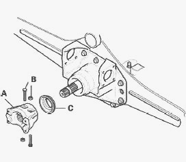
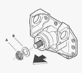
Remove screw B with its nut from flange A. Extract the flange and
recover the seal C. This will destroy the seal. Loosen and remove the
screws from the differential housing. Remove the differential housing.
Hold the differential housing in place with a sling or other suitable
device. Loosen and remove screws A to extract the two nut retainers B.
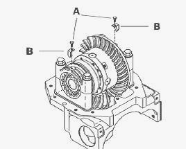
Before removing the screws, make indelible marks to mark the position of
the two half-bearings and the differential housing to avoid reassembling
the wrong way round. Also mark the area between the nuts and the
differential housing. Loosen the adjusting ring nuts. As the two nuts
are different, mark their position relative to the bevel ring gear.
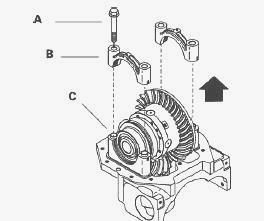
Remove the 4 screws A and the two half-bearings B. Check that rings C
stay in place in their seatings.
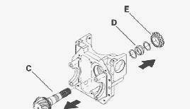
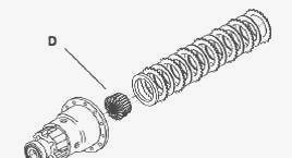
Remove the differential unit. From the ring gear side, remove and
recover spacer E with its set of rings D, washer F and the bearings
removed with the differential unit. Be careful not to invert the
bearings if they need to be reinstalled.
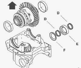
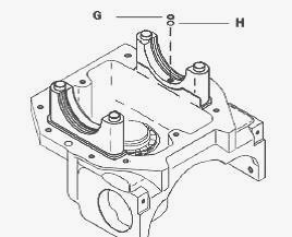
Recover washer G and "O" ring H from the bearing seating on the side of
the epicyclic ring gear.
Massey Ferguson 5465, 6465, 6475, 6485 -
Dismantling the pinion assembly
Install the differential assembly in a vice. Loosen the locknut. This
will irreparably destroy the nut. Extract nut A and recover retaining
washer B. Extract bevel gear C using a hammer. Ensure that the pinion
does not fall out. Recover the washers, flexible spacer D and internal
cone E from the tapered roller bearing.
Place the differential housing on a level surface and extract the
external cups from the roller bearing, using a drift or a hammer. Remove
the inside cone of the pinion's tapered roller bearing using a standard
puller. Recover the bearing cone and the shim located underneath it.
Check all the pinion parts for wear. The ring nut and the flexible
spacer must be replaced when refitting the assembly.
MF 5465, 6465, 6475, 6485 - Dismantling the
differential assembly
Recover the differential and secure it in a vice. Loosen the screws and
remove the bevel ring gear. This operation releases the two
half-bearings from the differential. Ensure that the internal parts do
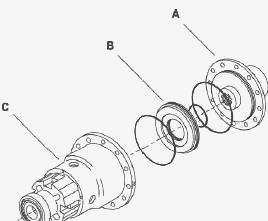
not fall out. Detach cover plate A from differential unit C, then
extract piston B. Recover the "O" rings from the cover plate and the
differential lock piston (internal and external housings).
Remove the plates, drive discs and sun gear D from the differential
unit. Disassemble the parts that have been removed and examine them
carefully, checking in particular for wear and ensuring that they are
functioning correctly.
Use a fine punch to extract the locating pin in order to remove the long
pin. Disassemble the planet carrier and recover the parts it contains:
planet gears, thrust washers, spider, sun gear. Check all parts for wear
and ensure they are functioning correctly. Extract the bearings from the
half-bearings and the cover plate using a three-point puller.
Massey Ferguson 5465, 6465, 6475, 6485 -
Install the pinion assembly
Place the differential housing on a workbench. Install the external cups
for the new bearings. To measure the distance, use special tool kit.
Insert the dummy pinion with its bearings and nut in the newly installed
roller bearing. Tighten without forcing to eliminate the backlash.
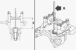
Install tools on the differential housing supports and tighten the
half-bearing screws. Assembly diagram for tools on the differential
housing supports. Using a depth gauge, measure distance B (between the
bearing pin and the bearing point of the pinion head or bearing base).
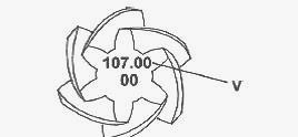
To determine the necessary thickness S between the pinion and the
bearing, subtract the value V engraved on the pinion head (V = specified
taper distance) from the measured value B: S = B - V. Select the
required thickness S from the range of shims available and insert the
chosen shim under the pinion head. Ensure that it is fitted correctly.
After inserting the correct shim with its chamfer facing the pinion,
force Install the bearing at the end of the pinion pin using special
tool and a press, ensuring that it is seated correctly. Install the
shims and a new flexible spacer. Systematically Install a new flexible
spacer. Insert the bevel gear assembly into the differential housing
(axle beam internal side) and the second bearing cone at the end of the
pinion, on the opposite side. Force Install the second bearing. It is
recommended that you exert resistance against the striking action of the
tool, by using a hammer for example.
Place a retaining washer and screw a new nut onto the end of the pinion.
Screw the nut on with the wrench while holding the pinion in place with
the tool. The tightening torque is determined by the bearing preload
measurement. Gradually tighten the nut. If too much tightening torque is
applied, replace the flexible spacer and restart the operation. When
checking bearing preload, it is advisable to gently tap both ends of the
pinion with a rubber hammer to make the bearing seating easier. Measure
the torque P of the tapered roller bearings of the pinion. Shimming is
carried out by gradually increasing the tightening torque of the nut,
taking care not to exceed the recommended value. All torques must be
measured without the seal. P = 1.82 to 2.72 Nm. When the torque value is
reached, peen the nut with a hammer and chisel.
________________________________________________________________________________
________________________________________________________________________________
________________________________________________________________________________________
 SPECS
SPECS LOADERS
 MAINTENANCE
 PROBLEMS
________________________________________________________________________________________
________________________________________________________________________________________
| MF TRACTORS SPECIFICATIONS |
 130
130 133
133 145
145 155
155 158
158________________________________________________________________________________________
 165
165 175
175 185
185 188
188 230
230________________________________________________________________________________________
 254
254 254S
254S 284S
284S 294
294 353
353________________________________________________________________________________________
 290
290 362
362 375
375 390
390 398
398________________________________________________________________________________________
 399
399 590
590 690
690 1010
1010 1030
1030________________________________________________________________________________________
 1020
1020 1150
1150 2620
2620 2640
2640 2645
2645________________________________________________________________________________________
 1540
1540 1736
1736 2660
2660 3065
3065 3095
3095________________________________________________________________________________________
 3650
3650 3680
3680 4255
4255 4355
4355 4370
4370________________________________________________________________________________________
 3630
3630 3635
3635 4245
4245 4445
4445 4609
4609________________________________________________________________________________________
 4710
4710 5435
5435 5475
5475 5610
5610 5711
5711________________________________________________________________________________________
 6150
6150 6170
6170 6180
6180 6270
6270 6290
6290________________________________________________________________________________________
 6445
6445 6499
6499 6614
6614 6713
6713 7465
7465________________________________________________________________________________________
 7495
7495 7614
7614 7622
7622 7715
7715 7726
7726________________________________________________________________________________________
 8210
8210 8270
8270 8650
8650 8727
8727 GC1705
________________________________________________________________________________________
| MF FRONT END LOADERS |
 1464 Loader
 1466 Loader
 1040 Loader
 1070 Loader
 905 Loader
________________________________________________________________________________________
 906 Loader
 915 Loader
 916 Loader
 921 Loader
 926 Loader
________________________________________________________________________________________
 931 Loader
 933 Loader
 936 Loader
 938 Loader
 939 Loader
________________________________________________________________________________________
 940 Loader
 941 Loader
 945 Loader
 946 Loader
 948 Loader
________________________________________________________________________________________
 949 Loader
 950 Loader
 951 Loader
 955 Loader
 956 Loader
________________________________________________________________________________________
 958 Loader
 960 Loader
 961 Loader
 965 Loader
 966 Loader
________________________________________________________________________________________
 968 Loader
 975 Loader
 976 Loader
 978 Loader
 985 Loader
________________________________________________________________________________________
 FL.3114 X
 FL.3419 X
 FL.3522
 FL.3615
 FL.3619
________________________________________________________________________________________
 FL.3817
 FL.3819
 FL.3823
 FL.4018
 FL.4121
 916X Loader
 921X Loader
 926X Loader
 931X Loader
 936X Loader
________________________________________________________________________________________
 941X Loader
 946X Loader
 951X Loader
 956X Loader
 988 Loader
________________________________________________________________________________________
 FL.4125
 FL.4227
 FL.4124
 FL.4220
 FL.4323
________________________________________________________________________________________
 FL.4327
 FL.4621
 FL.4624
 FL.4628
 FL.5033
________________________________________________________________________________________
 DL95 Loader
 DL100 Loader
 DL120 Loader
 DL125 Loader
 DL130 Loader
________________________________________________________________________________________
 DL135 Loader
 DL250 Loader
 DL260 Loader
 L90 Loader
 L100 Loader
________________________________________________________________________________________
 L105E Loader
 L210 Loader
 1014 Loader
 1016 Loader
 1462 Loader
________________________________________________________________________________________
 1525 Loader
 1530 Loader
 232 Loader
 838 Loader
 848 Loader
________________________________________________________________________________________
 246 Loader
 1036 Loader
 1038 Loader
 1080 Loader
 856 Loader
________________________________________________________________________________________
| MF TRACTORS MAINTENANCE |
 1010
1010 1020
1020 1030
1030 1035
1035 1040
1040________________________________________________________________________________________
 1045
1045 1080
1080 1085
1085 1120
1120 1125
1125________________________________________________________________________________________
 1140
1140 1160
1160 1165
1165 1180
1180 1190
1190________________________________________________________________________________________
 1205
1205 1210
1210 1215
1215 1220
1220 1225
1225________________________________________________________________________________________
 1230
1230 1233
1233 1235
1235 1240
1240 1260
1260________________________________________________________________________________________
| MF TRACTORS TROUBLESHOOTING | ||||
| 1652 | 1749 | 2620 | 2725 | 2805 |
| 3050 | 3120 | 3640 | 3709 | 4245 |
| 4455 | 5320 | 5455 | 5613 | 6150 |
| 6280 | 6480 | 6615 | 7618 | 7720 |