
________________________________________________________________________________
Massey Ferguson 5465, 6465, 6475, 6485 - Carraro differential unit
Massey Ferguson 5465, 6465, 6475, 6485 -
Carraro front axle differential unit reassembly
Mount the new tapered roller bearings on the half-bearings. Position one
of the half bearings on a workbench and install the internal parts
(thrust washer, sun gear, planet gears, spider) as shown in the figure.
Insert the pin into its housing, holding the planet gears and spider
correctly in place. Lock the pin by inserting the locating dowel in the
hole provided on the bearing and pin. Turn the pin manually to align the
hole of the dowel with that of the bearing. Definitively position the
locating dowel.
Position all the internal parts in the bearing: planet gears, discs and
counter-discs. Install new "O" rings in the seatings provided on the
piston and on the differential cover plate. Insert the piston and fit
the cover plate in the differential housing. Apply a film of Loctite 476
between the bevel ring gear and the differential housing surface.
Position the bevel ring gear on the cover plate, apply Loctite 270 to
the threads and attach the assembly, tightening the screws to a torque
of 70 Nm.
Massey Ferguson 5465, 6465, 6475, 6485 -
Install the differential housing assembly
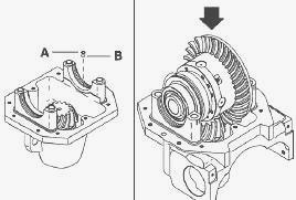
Install the external tapered roller bearing cups on the two differential
bearings and install the washer and spacer on the crownwheel and pinion
side with new seals, previously smeared with a thin layer of grease.
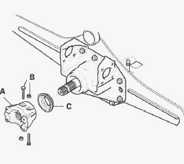
Before positioning the differential unit in the differential housing,
install a new seal B and washer A at the bearing base on the bevel ring
gear side, over the oil hydraulic port. Install the unit assembly on the
differential housing. Take care not to invert the external cups of the
tapered roller bearings and ensure that the bevel ring gear assembly is
fitted on the correct side.
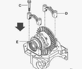
Move the differential assembly so that the bevel ring gear can be
positioned on the pinion. Ensure that all rings E are in position in
their seatings and place both half-bearings D on their seats, following
the marks made during disassembly. Lock the two half-bearings with their
screws C.
Assemble and tighten the two adjustment nuts in the differential housing
to eliminate the backlash and slightly preload the differential
bearings. As the two nuts are different, take care to return them to
their original positions relative to the bevel ring gear. Check that the
bearings are correctly mounted in their seats, and, if necessary, tap
them gently with a rubber hammer to secure them in place.
Place a dial gauge with a magnetic stand on the differential housing and
move the dial gauge feeler pin until it comes into contact with a ring
gear tooth at a 90 deg angle. Lock the pinion and move the ring gear
alternately to the right and left, using the dial gauge to measure the
backlash between the pinion and the ring gear. Repeat the operation on
at least two teeth, turning the ring gear, to calculate an average
value. Check that the measured backlash value is within the permissible
tolerances: 0.18 to 0.23 mm. Fine-tune the shimming by adjusting the two
nuts.
When tightening nuts, always remember that: if the measured backlash is
lower than the permissible tolerance, the nut on the bevel ring gear
side must be loosened and the opposite screw must be screwed to the same
value. If the measured backlash is higher than the permissible
tolerance, the nut on the side opposite the bevel ring gear side must be
loosened and the screw on the other side must be screwed to the same
value. When the backlash between the pinion and ring gear has been
adjusted, check that the bearing preload of the differential unit is
minimal. Repeat the sequence of steps described above until the required
conditions are met.
Once the correct backlash has been obtained between the pinion and ring
gear, measure the total bearing torque T (pinion-bevel ring gear
system). The measured value must remain within the following limits: T=
(P+1.82) to (P+2.12) N.m where P represents the actual measured pinion
torque. All torques must be measured without the seal. If the measured
value is outside the permissible tolerances, check the assembly of each
part carefully and adjust the differential housing adjustment nuts: if
the total torque is lower than the permissible values, tighten both nuts
identically without modifying the backlash between the pinion and ring
gear. If the total torque is higher than the permissible values, loosen
both nuts identically without modifying the backlash between the pinion
and ring gear.
To test the marking of the crownwheel and pinion teeth, apply a tiny
amount of paint to the ring gear. This marking test must be carried out
systematically on the bevel ring gear teeth and on each face. OK =
Correct contact.
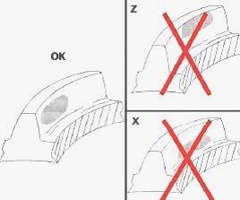
If the crownwheel and pinion are adjusted correctly, a uniform layer of
paint is left on the surfaces of the teeth: Z: Excessive contact at the
tip of the teeth. Move the pinion closer to the ring gear then move the
ring gear away to correct the backlash. X: Excessive contact at the base
of the teeth. Move the pinion away from the ring gear, then move the
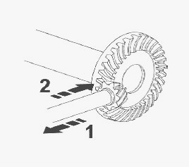
ring gear closer to correct the backlash. Corrective action: Move the
pinion in the direction of the arrow to adjust an X type contact. Move
the pinion in the direction of the arrow to adjust a Z type contact.
When the shimming procedure is complete, Install the nut retainers with
their screws and tighten to the required torque (13 Nm) using a torque
wrench. The nut and its corresponding counter-nut are different on the
ring gear side and the opposite side of the differential unit; turn the
nuts slightly to align them with their retainers.
Tighten the screws of the two half-bearings with a torque wrench to the
required torque (266 Nm). Before bringing two surfaces into contact,
ensure that both are perfectly clean. Degrease and clean them with
suitable cleaning products. Apply a thin film of Loctite 510 to the
mating surface between the axle beam and the differential housing.
Install the differential housing on the axle housing and screw to the
required torque (169 Nm). Install a new previously lubricated seal C on
the end of the pinion then install the flange A. Position the flange
screws B with their respective nuts. Tighten the screws and nuts with a
torque wrench to the required torque (57 Nm).
________________________________________________________________________________
________________________________________________________________________________
________________________________________________________________________________________
 SPECS
SPECS LOADERS
 MAINTENANCE
 PROBLEMS
________________________________________________________________________________________
________________________________________________________________________________________
| MF TRACTORS SPECIFICATIONS |
 130
130 133
133 145
145 155
155 158
158________________________________________________________________________________________
 165
165 175
175 185
185 188
188 230
230________________________________________________________________________________________
 254
254 254S
254S 284S
284S 294
294 353
353________________________________________________________________________________________
 290
290 362
362 375
375 390
390 398
398________________________________________________________________________________________
 399
399 590
590 690
690 1010
1010 1030
1030________________________________________________________________________________________
 1020
1020 1150
1150 2620
2620 2640
2640 2645
2645________________________________________________________________________________________
 1540
1540 1736
1736 2660
2660 3065
3065 3095
3095________________________________________________________________________________________
 3650
3650 3680
3680 4255
4255 4355
4355 4370
4370________________________________________________________________________________________
 3630
3630 3635
3635 4245
4245 4445
4445 4609
4609________________________________________________________________________________________
 4710
4710 5435
5435 5475
5475 5610
5610 5711
5711________________________________________________________________________________________
 6150
6150 6170
6170 6180
6180 6270
6270 6290
6290________________________________________________________________________________________
 6445
6445 6499
6499 6614
6614 6713
6713 7465
7465________________________________________________________________________________________
 7495
7495 7614
7614 7622
7622 7715
7715 7726
7726________________________________________________________________________________________
 8210
8210 8270
8270 8650
8650 8727
8727 GC1705
________________________________________________________________________________________
| MF FRONT END LOADERS |
 1464 Loader
 1466 Loader
 1040 Loader
 1070 Loader
 905 Loader
________________________________________________________________________________________
 906 Loader
 915 Loader
 916 Loader
 921 Loader
 926 Loader
________________________________________________________________________________________
 931 Loader
 933 Loader
 936 Loader
 938 Loader
 939 Loader
________________________________________________________________________________________
 940 Loader
 941 Loader
 945 Loader
 946 Loader
 948 Loader
________________________________________________________________________________________
 949 Loader
 950 Loader
 951 Loader
 955 Loader
 956 Loader
________________________________________________________________________________________
 958 Loader
 960 Loader
 961 Loader
 965 Loader
 966 Loader
________________________________________________________________________________________
 968 Loader
 975 Loader
 976 Loader
 978 Loader
 985 Loader
________________________________________________________________________________________
 FL.3114 X
 FL.3419 X
 FL.3522
 FL.3615
 FL.3619
________________________________________________________________________________________
 FL.3817
 FL.3819
 FL.3823
 FL.4018
 FL.4121
 916X Loader
 921X Loader
 926X Loader
 931X Loader
 936X Loader
________________________________________________________________________________________
 941X Loader
 946X Loader
 951X Loader
 956X Loader
 988 Loader
________________________________________________________________________________________
 FL.4125
 FL.4227
 FL.4124
 FL.4220
 FL.4323
________________________________________________________________________________________
 FL.4327
 FL.4621
 FL.4624
 FL.4628
 FL.5033
________________________________________________________________________________________
 DL95 Loader
 DL100 Loader
 DL120 Loader
 DL125 Loader
 DL130 Loader
________________________________________________________________________________________
 DL135 Loader
 DL250 Loader
 DL260 Loader
 L90 Loader
 L100 Loader
________________________________________________________________________________________
 L105E Loader
 L210 Loader
 1014 Loader
 1016 Loader
 1462 Loader
________________________________________________________________________________________
 1525 Loader
 1530 Loader
 232 Loader
 838 Loader
 848 Loader
________________________________________________________________________________________
 246 Loader
 1036 Loader
 1038 Loader
 1080 Loader
 856 Loader
________________________________________________________________________________________
| MF TRACTORS MAINTENANCE |
 1010
1010 1020
1020 1030
1030 1035
1035 1040
1040________________________________________________________________________________________
 1045
1045 1080
1080 1085
1085 1120
1120 1125
1125________________________________________________________________________________________
 1140
1140 1160
1160 1165
1165 1180
1180 1190
1190________________________________________________________________________________________
 1205
1205 1210
1210 1215
1215 1220
1220 1225
1225________________________________________________________________________________________
 1230
1230 1233
1233 1235
1235 1240
1240 1260
1260________________________________________________________________________________________
| MF TRACTORS TROUBLESHOOTING | ||||
| 1652 | 1749 | 2620 | 2725 | 2805 |
| 3050 | 3120 | 3640 | 3709 | 4245 |
| 4455 | 5320 | 5455 | 5613 | 6150 |
| 6280 | 6480 | 6615 | 7618 | 7720 |