
________________________________________________________________________________
Massey Ferguson 5465, 6465, 6475, 6480 - Carraro final drive unit
Before draining the oil, position the wheel hub with the plug at its
highest point and loosen the plug by several turns to release any
internal residual pressure, then loosen it completely. Turn the hub
again to position the plug at its lowest point. Completely drain the
oil. Loosen and remove the two planet carrier screws using a wrench.
Extract the planet carrier from the wheel hub. Place the planet carrier
on a workbench and check it for wear.
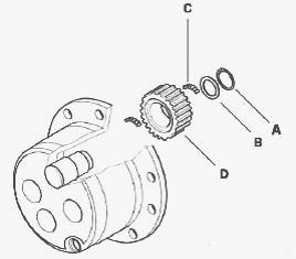
Replace the planet gears as necessary: extract circlip A from each
planet gear, remove washer B and extract planet gears D from their pins,
recover bearings C and check their condition. It is recommended that you
replace the bearings when installing new planet gears.
Wheel hub disassembly
Before disassembling the wheel hub, it is recommended that you attach it
with a belt or sling to a hoist or other suitable lifting device to
prevent it from falling accidentally, risking injury to the operator and
damage to the wheel hub. Some of the following illustrations may show
axles that differ slightly from your model, but the procedure is the
same. Insert a lever between the swivel housing and slide it into the
universal joint. Push on the joint with the lever in the direction of
the final drive to remove the circlip more easily. Remove and discard
the circlip. Remove and discard the washer. Remove and discard the two
star washers. Loosen and remove the screws from the ring gear carrier
assembly. To remove the ring gear assembly from its housing, screw at
least two of the screws that have just been removed into the threaded
extraction holes. While keeping an eye on the ring gear ports, avoid
positioning the screws on the cast iron notches.
Remove the ring gear carrier with the epicyclic ring gear. Remove the
snap ring and detach the ring gear carrier from the epicyclic ring gear.
Check the condition of the parts. If necessary, remove the locating
rings from the locking ring gear of the hub using a hammer and special
tool. Remove the wheel hub using levers and a hammer to facilitate the
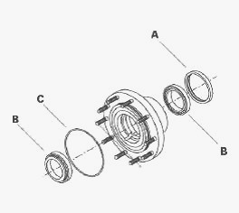
operation. Recover the bearing cone. Place the wheel hub on a level
surface and extract the seal ring (A) with a lever. This will destroy
the seal ring. Remove bearing cups B from either side of the hub using a
hammer and a suitable puller. Remove the bearing cone from the swivel
housing side using a suitable puller. Remove the "O" ring C from the
wheel hub.
Loosen and remove the screws from the upper and lower pivot pins. Before
removing the pivot pins, attach the swivel housing to a hoist or other
suitable lifting device with a belt or sling. Remove the pivot pins and
recover the Belleville washers. Mark the positioning of the two
Belleville washers, which are not identical. Remove the swivel housing
from the axle beam and the short shaft of the universal joint shaft.
Place the swivel housing on a level surface and extract the seal ring
with a lever. This will destroy the seal ring. Turn the swivel housing
to extract the ring using a drift and a hammer.
Massey Ferguson 5465, 6465, 6475, 6480 -
Dismantling the axle beam assembly
Separate the universal joint shaft from the axle beam. Extract seal ring
A from the axle beam with a lever. Remove the Belleville washers C from
the pivot pin housings inside the axle beam. Mark the positioning of the
two Belleville washers, which are not identical. This will destroy the
seal ring. Extract ring B from the axle beam using a suitable puller.
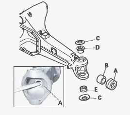
Check the ring before reassembling and only replace it if its state of
wear requires this. Extract the upper rings D and lower rings E from the
pivot pin housings F and pivot pins using a suitable puller. Extract the
nut and retaining washer from the taper pin. Remove the pin using a
hammer. Remove the pivot pin using a hammer or other soft object if
necessary.
MF 5465, 6465, 6475, 6480 - Reassembling the
axle beam assembly
Install the ring of the upper pivot pin on the axle beam using special
tool and a hammer. Insert the roller bearing cup on the lower part of
the axle beam using special tool and a hammer. Cool the arm pins to
under -100C before installing them in order to facilitate their
assembly. This can be achieved by completely immersing the arm pins in
liquid nitrogen. To purchase or hire liquid nitrogen, contact the
company "Air Liquide". It is advisable to wear protective gloves.
Install the ring on the axle beam using special tool and a hammer.
Install the seal on the axle beam. Fill the seal seating three quarters
full with grease. Lubricate the ring and the lip of the seal. Insert the
universal joint shaft into the axle beam.
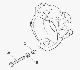
Reassembling the wheel hub assembly
Position screw A, nut B and washer C. If washer C is not fitted, the
axle will be damaged.
Force Install the ring in the swivel housing. Install the seal on the
swivel housing. Fill the seal seating three quarters full with grease.
Place the lower pivot pin on a workbench and install the ball joint cone
and a press. Apply a generous amount of grease to the pivot pin
housings. Install the Belleville washers on the pivot pin housings.
Attach the swivel housing assembly with a sling. Lubricate the seal lip
and protect the splined end of the shaft by wrapping adhesive tape
around it to protect the seal from damage. After assembly, completely
remove the adhesive tape. Install the swivel housing on the axle beam.
Install the two pivot pins, one upper and one lower, and tighten the
screws to the required torque using a torque wrench. Ensure that the
Belleville washers remain in place.
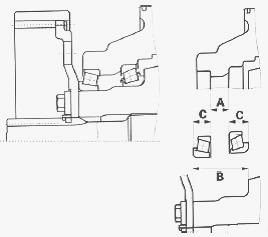
The special "Set Right" operation, which consists of shimming the
bearings, does not require any specific preload or setting. The required
values should always be checked before installing new parts. A = 08.450
to 08.500 mm. B = 54.775 to 54.825 mm. C = 23.070 to 23.172 mm.
Place the wheel hub on a workbench and install the two tapered roller
bearing cups and a press or hammer. Insert the lip seal into the wheel
hub. Install the bearing cone at the end of the pivot pin. Assemble the
hub on the pivot pin and fit the second bearing cone. Place the ring
gear carrier on a workbench and ensure that the rings are flush with the
ring gear carrier surface. The two rings must be positioned slightly
higher than the ring gear carrier surface to act as guide pins.
Pre-position the assembly consisting of the ring gear carrier and the
epicyclic ring gear with special snap ring.
Install the ring gear carrier assembly on the wheel hub using the two
shouldered rings as guide pins and tighten the corresponding screws
until the ring gear comes into contact with the wheel hub. Do not use
the two screws that were used to remove the ring gear assembly from its
housing when disassembling. Force Install all the rings. Install the
ring gear carrier screws and tighten to the required torque. Insert a
lever between the swivel housing and slide it into the universal joint.
Push on the joint with the lever in the direction of the final drive to
remove the shaft and facilitate reassembly of the circlip. Install two
new star washers on the shaft. Check that the two washers are correctly
positioned. Install a new washer, positioning it so that the groove
faces outwards. Install the snap ring. Take care not to damage it during
assembly. Carefully push the universal joint and ensure that the circlip
is correctly positioned in the groove of the washer.
Massey Ferguson 5465, 6465, 6475, 6480 -
Reassembling the final drive assembly
Recover all final drive parts. Place the planet carrier on a workbench.
Into the planet carrier pins insert: the lower bearings, the planet
gears and then the upper bearings. Install the thrust washers with their
circlips. Using a torque wrench, tighten the screws to the required
torque. Install a new "O" ring on the wheel hub. Install the final drive
on the hub. Using a torque wrench, tighten the screws to the required
torque.
Wheel alignment
Place two identical straight bars, each one metre long, along the sides
of the ring gear and lock them on the wheel hub stud using two nuts.
Measure the distance M in mm between the ends of the bars. Keep the
minimum value by oscillating the measurement point.
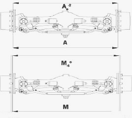
Ensure that the deviation in measurement A between the ends of the wheel
hub diameters does not exceed the permissible values. Measured value M
taken at the ends of the bars must depend on the ratio between the
length of the bar and the diameter of the flange: Alignment (see chapter
8) = A0-2. Measurement deviation = M0-5. If the alignment is not
correct, adjust the selector rails by screwing or unscrewing both tie
rods equally, using two wrenches, until the alignment is within the
permitted values. Once adjustment is complete, screw the locknuts of the
selector rails to the required torque.
Adjusting the steering angle
Use the bars fitted to adjust alignment and a long bar pressing against
the machined part of the central body (gear side) so that the two bars
form an acute angle corresponding to the maximum steering lock position.
Adjust the goniometer to the required steering angle and position it on
the long bar. Move one side of the ring gear to obtain the angle defined
by the goniometer and formed by the ring gear and the long bar. Adjust
the mechanical steering stop by tightening or loosening the special
screws, then lock them to the required torque using the counter-nut.
Lock steering in the other direction and repeat this procedure.
________________________________________________________________________________
________________________________________________________________________________
________________________________________________________________________________________
 SPECS
SPECS LOADERS
 MAINTENANCE
 PROBLEMS
________________________________________________________________________________________
________________________________________________________________________________________
| MF TRACTORS SPECIFICATIONS |
 130
130 133
133 145
145 155
155 158
158________________________________________________________________________________________
 165
165 175
175 185
185 188
188 230
230________________________________________________________________________________________
 254
254 254S
254S 284S
284S 294
294 353
353________________________________________________________________________________________
 290
290 362
362 375
375 390
390 398
398________________________________________________________________________________________
 399
399 590
590 690
690 1010
1010 1030
1030________________________________________________________________________________________
 1020
1020 1150
1150 2620
2620 2640
2640 2645
2645________________________________________________________________________________________
 1540
1540 1736
1736 2660
2660 3065
3065 3095
3095________________________________________________________________________________________
 3650
3650 3680
3680 4255
4255 4355
4355 4370
4370________________________________________________________________________________________
 3630
3630 3635
3635 4245
4245 4445
4445 4609
4609________________________________________________________________________________________
 4710
4710 5435
5435 5475
5475 5610
5610 5711
5711________________________________________________________________________________________
 6150
6150 6170
6170 6180
6180 6270
6270 6290
6290________________________________________________________________________________________
 6445
6445 6499
6499 6614
6614 6713
6713 7465
7465________________________________________________________________________________________
 7495
7495 7614
7614 7622
7622 7715
7715 7726
7726________________________________________________________________________________________
 8210
8210 8270
8270 8650
8650 8727
8727 GC1705
________________________________________________________________________________________
| MF FRONT END LOADERS |
 1464 Loader
 1466 Loader
 1040 Loader
 1070 Loader
 905 Loader
________________________________________________________________________________________
 906 Loader
 915 Loader
 916 Loader
 921 Loader
 926 Loader
________________________________________________________________________________________
 931 Loader
 933 Loader
 936 Loader
 938 Loader
 939 Loader
________________________________________________________________________________________
 940 Loader
 941 Loader
 945 Loader
 946 Loader
 948 Loader
________________________________________________________________________________________
 949 Loader
 950 Loader
 951 Loader
 955 Loader
 956 Loader
________________________________________________________________________________________
 958 Loader
 960 Loader
 961 Loader
 965 Loader
 966 Loader
________________________________________________________________________________________
 968 Loader
 975 Loader
 976 Loader
 978 Loader
 985 Loader
________________________________________________________________________________________
 FL.3114 X
 FL.3419 X
 FL.3522
 FL.3615
 FL.3619
________________________________________________________________________________________
 FL.3817
 FL.3819
 FL.3823
 FL.4018
 FL.4121
 916X Loader
 921X Loader
 926X Loader
 931X Loader
 936X Loader
________________________________________________________________________________________
 941X Loader
 946X Loader
 951X Loader
 956X Loader
 988 Loader
________________________________________________________________________________________
 FL.4125
 FL.4227
 FL.4124
 FL.4220
 FL.4323
________________________________________________________________________________________
 FL.4327
 FL.4621
 FL.4624
 FL.4628
 FL.5033
________________________________________________________________________________________
 DL95 Loader
 DL100 Loader
 DL120 Loader
 DL125 Loader
 DL130 Loader
________________________________________________________________________________________
 DL135 Loader
 DL250 Loader
 DL260 Loader
 L90 Loader
 L100 Loader
________________________________________________________________________________________
 L105E Loader
 L210 Loader
 1014 Loader
 1016 Loader
 1462 Loader
________________________________________________________________________________________
 1525 Loader
 1530 Loader
 232 Loader
 838 Loader
 848 Loader
________________________________________________________________________________________
 246 Loader
 1036 Loader
 1038 Loader
 1080 Loader
 856 Loader
________________________________________________________________________________________
| MF TRACTORS MAINTENANCE |
 1010
1010 1020
1020 1030
1030 1035
1035 1040
1040________________________________________________________________________________________
 1045
1045 1080
1080 1085
1085 1120
1120 1125
1125________________________________________________________________________________________
 1140
1140 1160
1160 1165
1165 1180
1180 1190
1190________________________________________________________________________________________
 1205
1205 1210
1210 1215
1215 1220
1220 1225
1225________________________________________________________________________________________
 1230
1230 1233
1233 1235
1235 1240
1240 1260
1260________________________________________________________________________________________
| MF TRACTORS TROUBLESHOOTING | ||||
| 1652 | 1749 | 2620 | 2725 | 2805 |
| 3050 | 3120 | 3640 | 3709 | 4245 |
| 4455 | 5320 | 5455 | 5613 | 6150 |
| 6280 | 6480 | 6615 | 7618 | 7720 |