
________________________________________________________________________________
Massey Ferguson 5465, 6465, 6475, 6480 - Carraro front axle transmission shaft bearings
The MF 5465, 6465, 6475, 6480 tractors are fitted with a fixed Carraro
front axle. Drive is transmitted from the front axle clutch located in
the rear axle via a transmission shaft. On 6-cylinder tractor engine
models, the transmission shaft has a universal joint and the front axle
pivot is raised. The shaft is divided into two sections. The section
linked to the 4WD unit by a sleeve is fixed.
The front part of the tractor transmission shaft has a universal joint,
allowing the axle to oscillate on its raised pin. The two sections of
the transmission shaft are linked by a castellated nut (11) and
supported by a bearing (6) at gearbox level. The front frame supports
the front axle pivot. The pivot front bearing is removable on all
models, while the rear bearing is part of the front frame assembly.
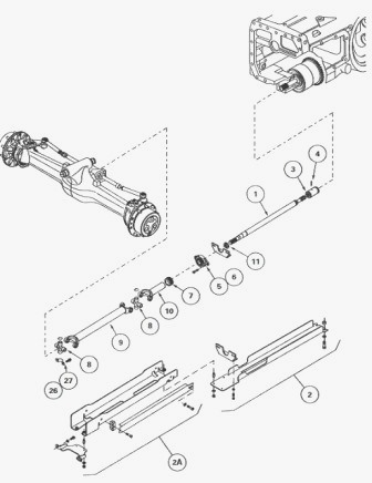
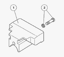
Parts list (Carraro 20.19 front axle) - (1) Straight
shaft (2) Guard (2A) Guard (3) Sleeve (4) Screw (5) Central bearing (6)
Bearing (7) Dust seal nut (8) Spider (9) Shaft (10) Sleeve (11)
Castellated locknut (12) Front frame (13) Chamfered washer (14) Washer
(15) Front bearing (16) Seal (17) Ring (18) Ring (19) Plug (20) Circlip
(21) Screw (22) Front axle (23) Grease nipple (24) Union (25)
Lubrication pipe (26) Flanges (27) Screw
MF 5465, 6465, 6475, 6480 - Disassembling and
reassembling the 4WD transmission shafts and the universal joint spiders
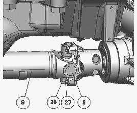
Disassembling the universal joint shaft - Chock the rear wheels and
apply the hand brake. Remove the guards (2) (2A). Unscrew the dust seal
nut (7). Remove the screws (27) and the flanges (26). Move the universal
joint shaft (9) and spider (8) assembly away from the drive pinion
carrier. Remove the shaft. If there is not enough room to push the
universal joint shaft backwards for removal, disassemble the central
bearing and the straight shaft (1). The spiders are replaceable. They
are listed in the parts book.
If the spiders need to be replaced, carefully check the condition of the
end clevises where the spider catches are located. Remove any traces of
impact or sharp edges. Thoroughly clean the groove of each circlip.
After assembly, check that the circlips are properly positioned in their
respective grooves. If necessary, and to facilitate mounting of the
universal joint shaft on the drive pinion carrier, raise the front
wheels using a jack with sufficient lifting capacity, positioned along
the axis of the axle housing.
Replace the dust seal nut (7). Use a makeshift tapered tool to refit the
dust seal nut (7) on the shaft (1). Smear the front splines of the
straight shaft with molybdenum sulphide grease or equivalent. Refit the
universal joint shaft (9). Attach the front spider (8) to the plate of
the drive pinion carrier using the flanges (26) and washer-head screws
(27) that have been lightly smeared with Loctite 241 or equivalent and
tightened to a torque of 34-41 Nm. Moderately tighten the dust seal nut
(7). Using a grease gun, lubricate the sleeve (10) and refit the guards
(2) and (2A).
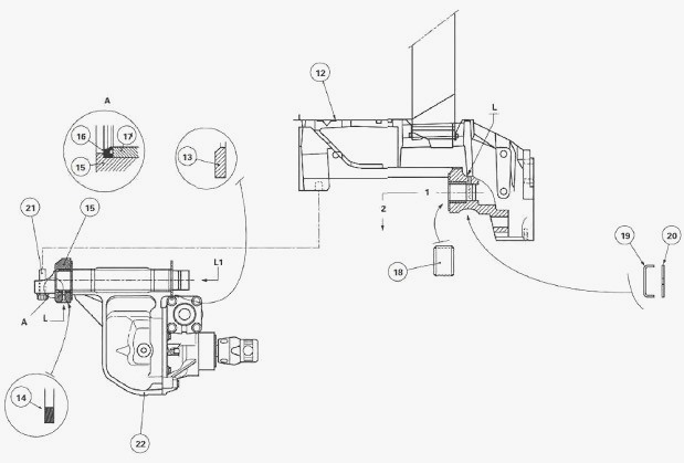
Massey Ferguson 5465, 6465, 6475, 6480 -
Straight shaft and bearing
Disassembling - Remove the guards (2) (2A) and the universal joint shaft
assembly. Remove the screw (4) and slide the sleeve (3) towards the
front of the straight shaft. Remove the central bearing (5), bearing (6)
and straight shaft (1) assembly. Separate the support (5) from the
bearing (6). Unscrew the castellated nut (11) using a suitable wrench.
Remove the bearing from the straight shaft.
Reassembling - Check the parts. Replace those that are defective.
Install bearing (6) on the straight shaft with the offset turned
rearwards. Tighten the nut with a suitable wrench. Assemble the support
(5) on the bearing (6). Tighten the screws. Reinstall the central
bearing, bearing (6) and straight shaft (1) assembly. Smear the rear
splines of the straight shaft (1) with molybdenum sulphide grease or
equivalent. Slide the sleeve (3) towards the rear of the straight shaft.
Refit the screw (4). Replace it if it is in a poor condition. Reinstall
the universal joint shaft assembly. Reinstall the guards (2) (2A).
Massey Ferguson 5465, 6465, 6475, 6480 -
Removing and install the bearing support and Carraro front axle
Remove the 45 kg front weights (if fitted). Immobilise the MF 5465,
6465, 6475, 6480 tractor. Apply the hand brake. Place safety chocks on
either side of the rear wheels. Some tractors may be fitted with a front
power take-off. In this case, it will be necessary to remove it in order
to separate the front axle from the frame (12). In certain conditions,
the centre weight (1) of 100 kg may obstruct the removal of the bearing
support. For this configuration, strip out the internal parts at the
lower part of the grille to gain access to the weight. Take out the
central M20 screw (2) and lift the weight slightly using a suitable
lifting tool to release it from the support.
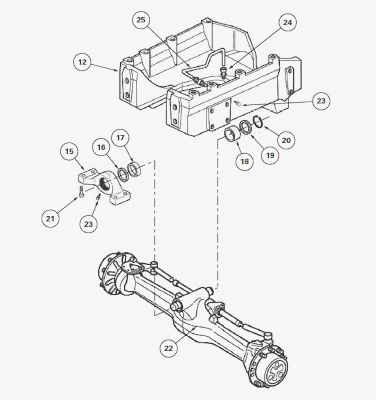
Removing the support (15) and the front axle. Remove the guards (2)
(2A). Raise the tractor along the axis of the front axle housing using a
jack with sufficient lifting capacity. Remove the front wheels. Mark the
steering hoses connection and detach them from the ram. Disconnect the
front differential lock control hose. Sling the front axle using
suitable straps. Remove the screws (21). Pull the front axle assembly
complete with bearing support (15) forwards along the axis of the axle
beam (position 1) and remove the front axle (position 2). Note the
features, order and position of the washers (13) (14) and the direction
of the chamfers and remove them.
Clean all components and check the condition of: the pivot pin at each
end, the washers (13) (14), the friction rings (17) (18), the seal (16).
Slide the washers (13) (14) lightly smeared with bearing grease onto the
front and rear ends of the pivot pin. Position the washers in the order.
Sling the front axle. Moderately lubricate the ends of the pivot pin and
Install the support (15) at the front of the pivot pin. Before refitting
the front axle assembly, check that there is no excess grease in the
cavity of the second axle beam pivot on the front frame.
When refitting the front axle assembly, any such excess grease will be
compressed, and may hinder insertion of the pivot pin into its bearing.
Reinstall the front axle and support (15) assembly. Push the assembly
hard until it comes into contact with the second axle beam pivot. Thrust
the support (15) against the front axle assembly (22) to eliminate the
clearance between supports and axle housing as much as possible. Install
the screws lightly smeared with Loctite 270 or equivalent and tighten to
a torque of 520-640 Nm.
Check that the front face of the pivot pin is almost level with the
front edge "F" of the bearing support (15). Visually check for the
presence of the grease nipple on the left-hand side of the front frame
(12) (second axle beam pivot) and on the support (15) (first axle beam
pivot). Reconnect the hoses (using marks made during disassembly): of
the steering ram, of the front differential lock. Reinstall the wheels.
Remove the axle stand and take away the jack. Tighten the nuts to a
torque of 640-680 Nm. Reinstall the centre weight. Tighten the central
screw to a torque of 100-150 Nm and secure the front weights (depending
on equipment fitted). Reinstall the universal joint shaft and the
guards. Remove the safety chocks and release the hand brake. Using a
grease gun, lubricate the friction rings (17) (18) of the axle beam
pivots.
MF 5465, 6465, 6475, 6480 - Replacing the
friction rings and seal
Front bearing
Disassembling - Only remove the bearing support (15). Extract and
discard the ring (17). Drive out and discard the seal (16).
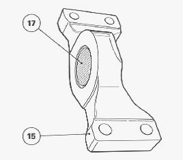
Reassembling - Clean and check all components. Replace those that are
defective. Check that the lubrication lines in the support are not
blocked.
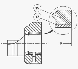
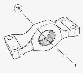
Using a press and a suitable fixture, Install the seal (16), positioned
correctly, and the ring (17) level with face "F" of the support (15),
with the lubrication port "T" connecting with the line.
To work on the ring (18) of the second axle beam pivot, the first axle
beam pivot and the front axle must be removed.
Rear bearing
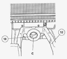
Disassembling - Drive out the ring (18) using a makeshift tool. The
circlip (20) and the plug (19) are not considered to be wearing parts.
It is therefore unlikely that they will need replacing.
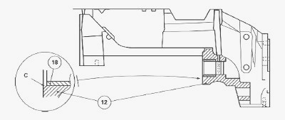
Reassembling - Using a makeshift fitting drift, Install the ring (18)
onto the frame (12) level with the chamfer "C".
________________________________________________________________________________
________________________________________________________________________________
________________________________________________________________________________________
 SPECS
SPECS LOADERS
 MAINTENANCE
 PROBLEMS
________________________________________________________________________________________
________________________________________________________________________________________
| MF TRACTORS SPECIFICATIONS |
 130
130 133
133 145
145 155
155 158
158________________________________________________________________________________________
 165
165 175
175 185
185 188
188 230
230________________________________________________________________________________________
 254
254 254S
254S 284S
284S 294
294 353
353________________________________________________________________________________________
 290
290 362
362 375
375 390
390 398
398________________________________________________________________________________________
 399
399 590
590 690
690 1010
1010 1030
1030________________________________________________________________________________________
 1020
1020 1150
1150 2620
2620 2640
2640 2645
2645________________________________________________________________________________________
 1540
1540 1736
1736 2660
2660 3065
3065 3095
3095________________________________________________________________________________________
 3650
3650 3680
3680 4255
4255 4355
4355 4370
4370________________________________________________________________________________________
 3630
3630 3635
3635 4245
4245 4445
4445 4609
4609________________________________________________________________________________________
 4710
4710 5435
5435 5475
5475 5610
5610 5711
5711________________________________________________________________________________________
 6150
6150 6170
6170 6180
6180 6270
6270 6290
6290________________________________________________________________________________________
 6445
6445 6499
6499 6614
6614 6713
6713 7465
7465________________________________________________________________________________________
 7495
7495 7614
7614 7622
7622 7715
7715 7726
7726________________________________________________________________________________________
 8210
8210 8270
8270 8650
8650 8727
8727 GC1705
________________________________________________________________________________________
| MF FRONT END LOADERS |
 1464 Loader
 1466 Loader
 1040 Loader
 1070 Loader
 905 Loader
________________________________________________________________________________________
 906 Loader
 915 Loader
 916 Loader
 921 Loader
 926 Loader
________________________________________________________________________________________
 931 Loader
 933 Loader
 936 Loader
 938 Loader
 939 Loader
________________________________________________________________________________________
 940 Loader
 941 Loader
 945 Loader
 946 Loader
 948 Loader
________________________________________________________________________________________
 949 Loader
 950 Loader
 951 Loader
 955 Loader
 956 Loader
________________________________________________________________________________________
 958 Loader
 960 Loader
 961 Loader
 965 Loader
 966 Loader
________________________________________________________________________________________
 968 Loader
 975 Loader
 976 Loader
 978 Loader
 985 Loader
________________________________________________________________________________________
 FL.3114 X
 FL.3419 X
 FL.3522
 FL.3615
 FL.3619
________________________________________________________________________________________
 FL.3817
 FL.3819
 FL.3823
 FL.4018
 FL.4121
 916X Loader
 921X Loader
 926X Loader
 931X Loader
 936X Loader
________________________________________________________________________________________
 941X Loader
 946X Loader
 951X Loader
 956X Loader
 988 Loader
________________________________________________________________________________________
 FL.4125
 FL.4227
 FL.4124
 FL.4220
 FL.4323
________________________________________________________________________________________
 FL.4327
 FL.4621
 FL.4624
 FL.4628
 FL.5033
________________________________________________________________________________________
 DL95 Loader
 DL100 Loader
 DL120 Loader
 DL125 Loader
 DL130 Loader
________________________________________________________________________________________
 DL135 Loader
 DL250 Loader
 DL260 Loader
 L90 Loader
 L100 Loader
________________________________________________________________________________________
 L105E Loader
 L210 Loader
 1014 Loader
 1016 Loader
 1462 Loader
________________________________________________________________________________________
 1525 Loader
 1530 Loader
 232 Loader
 838 Loader
 848 Loader
________________________________________________________________________________________
 246 Loader
 1036 Loader
 1038 Loader
 1080 Loader
 856 Loader
________________________________________________________________________________________
| MF TRACTORS MAINTENANCE |
 1010
1010 1020
1020 1030
1030 1035
1035 1040
1040________________________________________________________________________________________
 1045
1045 1080
1080 1085
1085 1120
1120 1125
1125________________________________________________________________________________________
 1140
1140 1160
1160 1165
1165 1180
1180 1190
1190________________________________________________________________________________________
 1205
1205 1210
1210 1215
1215 1220
1220 1225
1225________________________________________________________________________________________
 1230
1230 1233
1233 1235
1235 1240
1240 1260
1260________________________________________________________________________________________
| MF TRACTORS TROUBLESHOOTING | ||||
| 1652 | 1749 | 2620 | 2725 | 2805 |
| 3050 | 3120 | 3640 | 3709 | 4245 |
| 4455 | 5320 | 5455 | 5613 | 6150 |
| 6280 | 6480 | 6615 | 7618 | 7720 |