
________________________________________________________________________________
Massey Ferguson 5445, 5455, 6460 - Dana differential
The crownwheel and pinion assembly containing the differential lock
mechanism (Hydraulic lock) is fitted in a housing (7) comprising two
half-bearings (43) fixed by screws (42). The pinion is positioned at the
rear of the housing on two opposing tapered roller bearings. It is
adjusted in position using shims (8) located behind the head bearing.
The bearings are adjusted using shims (2) inserted between the spacer
(45) (if Installed) and the bearing cone (5). Tightness is ensured by a
lip seal (4) and an "O" ring (40) fitted on the pinion. The differential
comprises two planet gears (38) and a pin (36). The ring gear/pinion
clearance is obtained using shims (22) placed behind the cup (29). The
housing and ring gear assembly preload is obtained using the spline nut
(32).
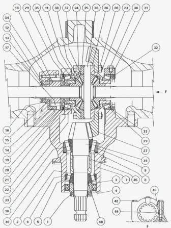
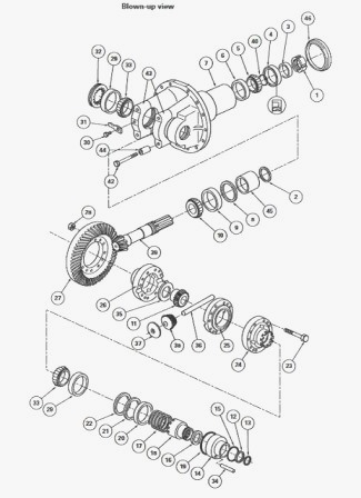
Dana differential parts list - (1) Nut (2) Shim(s) (3)
Spacer (4) Seal (5) Bearing cone (6) Bearing cup (7) Housing (8) Shim(s)
(9) Bearing cup (10) Bearing cone (11) Sun gear (12) Tab washer (13)
Snap ring (14) Piston (15) "O" ring (16) Friction washer (17) Spring
(18) Mobile dog clutch (19) "O" ring (20) Guide washer (21) Washer (22)
Shim(s) (23) Screw (24) Fixed dog clutch (25) Half-unit (26) Half-unit
(27) Ring gear (28) Nut (29) Bearing cup (30) Screw (31) Lock (32)
Spline nut (33) Bearing cone (34) Centring pin (35) Washer (36) Planet
gear pin (37) Spherical washer (38) Planet gear (39) Pinion (40) "O"
ring (42) Bearing screw (43) Half-bearing (44) Locating ring (45) Spacer
(46) Deflector
MF 5445, 5455, 6460, 6470 - Disconnecting the Dana
front axle and frame
Drain the axle housing. Disconnect the axle and its bearings from the
front frame. Removing the swivel housings, wheel hubs and transmissions.
Extract the steering ball joints. Using a suitable sling, support and
take off the complete right and left-hand swivel housing assemblies.
Removing the drive pinion carrier
Take off the swivel housing, wheel hub and transmission assemblies.
Remove the screws from the ram and remove the ram. Remove the screws.
Loosen and remove the drive pinion carrier. If necessary, remove the
deflector (46).
Massey Ferguson 5445, 5455, 5460, 6460, 6470 - Removing
the Dana differential unit
Place the housing (7) in a vice fitted with soft jaws. Take out the
screw (30) and its lock (31). Take off the spline nut (32) using the
special makeshift wrench. Take out the four screws (42). Take off the
half-bearings (43). Remove the differential assembly complete with cones
(33) and cups (29). Separate the cups from the cones. Remove the shim(s)
(22) used to adjust the backlash. Pair up the bearing cones and cups in
they are to be re-used.
Disassembling the planet gears and sun gears
Place the differential unit in a vice fitted with soft jaws. Before
disassembling, mark the position of the half-units (25) (26) and the
fixed dog clutch (24) with paint for reassembly in their initial
positions.
Removing the ring gear - Take off the screws (23) and nuts (28). Remove
the ring gear. Disassembling the planet gears and sun gears - Take off
the screws (23) and nuts (28). Separate the half-units (25) (26) and the
fixed dog clutch (24). Remove the sun gear (11) and the washer (35).
Take out the pin (36), planet gears (38) and spherical washers (37). If
required, extract the bearing cones (33) on the half-unit (26) and on
the fixed dog clutch (24).
MF 5445, 5455, 5460, 6460, 6470 - Removing the
differential lock
Using tool centred correctly, compress the spring (17) until the thrust
washer (21) is free. Take off the washer and gradually release the
spring. Take off the tool along with the guide washer (20) and spring.
Take off the snap ring (13). Remove the mobile dog clutch (18), the
friction washer (16) and the tab washer (12). Drive out the piston (14).
Discard the "O" rings (15) (19).
Removing the pinion
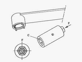
Loosen the pinion by turning clockwise, using special makeshift sleeve
"C". From the front of the housing, extract the pinion, cone (10),
spacer (45), shims (2) and "O" ring (40). Separate the pinion and seal
(40), and remove the shims (2) and the spacer (45). Extract the cone
(10) from the pinion. Drive out the cup (9) and remove the shims (8).
Remove the spacer (3), and extract the seal (4). Remove the cone (5).
Drive out the cup (6).
Adjusting the position – Shimming and
reinstall the pinion
Clean the components and replace those that are defective. Check that
the differential lock hydraulic channel is not blocked in the housing.
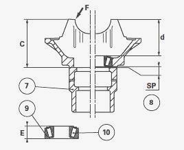
Adjust the position of the pinion. The thickness of shims required to
position the pinion correctly is calculated as follows: SP = C - E (d ±
r). SP: Thickness of shims required (8). C: Value measured between the
mating face of the cup and machined face "F". d: Pinion nominal
positioning dimension: 118 mm ± 0.10. E: Thickness of the bearings (9)
(10). r: Actual value marked on the pinion. This value may be positive
or negative (to be added or subtracted from the nominal value d). Using
a depth gauge, measure values C and E. Ensure the cone (10) is correctly
seated in the cup (9). After measuring the values, apply the formula to
determine the thickness of shims required. Install the cone (10) up
against the shoulder on the pinion (39) using a press and a suitable
fitting. Position the thickness of shims (8) calculated previously into
the housing. Install the cup (9) using a suitable fitting and shim the
bearings (5) (6) and (9) (10).
Shimming - In the housing (7), position the prepared pinion prepared up
against the cylindrical sleeve "M" as shown in pic. Press hard on the
housing while turning it several times in order to seat the bearing cone
(10) correctly in the bearing cup (9). Slide on the spacer (45), with
its chamfer facing towards the splines of the pinion.
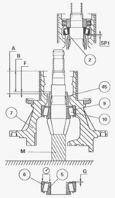
Using a depth gauge, measure value F according to the formula A - B.
Press hard on the cup (6), turning it alternately to the right and left
to correctly seat the cone (5). Measure value G. Calculate the thickness
of shims SP1 according to the formula: G - F. Position the cup (6) up
against the housing. Slide the shims (2) calculated during step onto the
pinion. Install the cone (5) and the lubricated seal (40). Grease the
lips of the seal (4) and Install it home in the shoulder using a
makeshift drift. Install the spacer (3). Install the nut (1). Using the
special sleeve and a torque wrench, turn the pinion until the following
tightening torque is obtained: 360-400 Nm. Check the pinion rotational
torque.
Checking the pinion rotational torque: Turn the pinion several turns
using a dial-type torque wrench and the special sleeve. Check that the
rotational torque is 2 to 4 Nm. After checking the torque, take off and
degrease the nut (1) and lightly smear it with Loctite 270 or
equivalent.
Massey Ferguson 5445, 5455, 5460, 6460, 6470 - Reinstall
the differential lock
Clean and check all components. Replace those that are defective.
Install the friction washer (16) to the mobile dog clutch (18). Install
the assembly in the piston (14). Install the tab washer (12) and
position the snap ring (13) in the groove of the mobile dog clutch. In
the housing without seals, provisionally Install the piston (14) with
the mobile dog clutch (18). The pin (34) is force-fitted in the piston.
Check - Ensure that the piston and pin slide freely in the housing.
After checking, remove the piston fitted with the mobile dog clutch.
Install the new "O" rings (15) (19). Position and fit the piston and
mobile dog clutch assembly by tapping around the rim with a plastic
hammer. Position the spring (17) and washer (20) with the shoulder
turned towards the spring. Compress the assembly using tool MF 471 until
the washer (21) slides freely in the groove of the housing. Loosen the
tool carefully so that the spring does not jump out.
MF 5445, 5455, 5460 6460, 6470 - Reassembling planet
gears and sun gears
Check and clean the components. Replace any defective parts.
Reassembling planet gears and sun gears - If it is necessary to replace
the bearings (29) (33), fit a cone (33) onto the half-unit (26) and
another cone onto the fixed dog clutch (24) using a press and a suitable
fitting. Assemble the half-unit (25) in the dog clutch (24), according
to the marks made during disassembly. Position the washer (35) on the
sun gear (11) and position the assembly in the half-unit (25), while
inserting the washer tab into one of the half-unit holes. Position the
planet gears (38) and washers (37) on the pin (36). Next, position the
assembly in the half-unit (25), while turning the tabs of the washers
(37) into the holes of the half-unit (25). Install the other washer (35)
on the other sun gear (11). Install the assembly in the half-unit (26)
according to the position of the tab of the washer (35). Position the
half-unit (26) assembly on the half-unit (25) according to the marks
made during disassembly.
Reinstall the ring gear - Any replacement of the ring gear (27)
automatically entails replacing the pinion (39). The same number is
engraved onto the pinion and ring gear. They must be fitted as pairs.
Clean the mating faces of the ring gear and differential unit. Degrease
the new screws and nuts and smear the threads of each screw with Loctite
270 or equivalent. Secure the two half-units (25) (26), fixed dog clutch
(24) and ring gear using screws and nuts (28) tightened to a torque of
82-90 Nm.
Reinstall and shimming the differential unit
Position the cups (29) on their cones (33). Install the shims (22)
recovered at disassembly up against the washer (21). Place the ring gear
assembly in the housing (7). Check that the locating rings (44) are
present. Position the half-bearings (43). Moderately tighten the screws
(42) so that the cups (29) fit freely with no play. Install the unit
horizontally in a vice with soft jaws, with the ring gear facing
upwards.
Shimming - Before shimming the differential unit, check that the ring
gear is not constrained on the pinion. Position a dial gauge. Tighten
the nut (32) and turn the ring gear (27) several turns to correctly seat
the cones in the cups. Retighten the nut to eliminate the axial
clearance. After eliminating the axial clearance, tighten the nut (32)
three more notches to obtain the correct preload.
Checking the backlash
Check the backlash using a dial gauge, moving it both ways around the
ring gear without causing the pinion to turn. Take three readings at
three equidistant points. Calculate the average of the three readings to
obtain a backlash between 0.18 and 0.23 mm. If the value measured is too
high, reduce the thickness of the shims (22), and if it is too low,
increase the thickness of the shims to obtain the correct backlash.
Repeat the differential unit shimming operation. Remove the screws (42)
one by one from the bearings, smear with Loctite 270 and tighten to a
torque of 115-127 Nm. Reassemble the lock (31) with the screw (30)
smeared with Loctite 270 and tighten to a torque of 16-25 Nm. Lock the
nut (32) by folding the lock tab into the corresponding spline.
Piston tightness test
On the differential lock supply union, Install a pressure gauge fitted
with a valve whose tightness has been checked beforehand. Supply the
system with compressed air at a pressure of approximately 5 bar and
check the reaction of the piston (14). Lower the pressure to 0.3 bar and
close the valve. No drop in pressure should be recorded on the pressure
gauge for approximately one minute. Remove the pressure gauge and valve
assembly.
Massey Ferguson 5445, 5455, 5460, 6460, 6470 - Reinstall
the drive pinion carrier
Check and clean the components. Replace any defective parts. Check for
the presence of the rings on the axle housing. Smear the mating face of
the differential housing on the axle housing with a sealing product,
Loctite 510 or equivalent, and tighten two diametrically opposed guide
studs. Reinstall the drive pinion carrier. Take out the guide studs.
Install and tighten the screws to a torque of 125-140 Nm. Reinstall the
steering ram. Smear the screws with Loctite 270 and tighten them to
180-200 Nm. Reinstall swivel housings, wheel hubs and transmissions -
Using a suitable sling, support and then refit the complete right and
left-hand swivel housing assemblies.
Assembling the front axle and frame
Connect the axle and its bearings to the front frame. Top up the oil
level in the front axle housing and check the oil level in the final
drives. Carry out a road test for the front axle and differential lock
control. Check tightness: of the seals and the differential housing
mating face, hydraulic unions.
________________________________________________________________________________
________________________________________________________________________________
________________________________________________________________________________________
 SPECS
SPECS LOADERS
 MAINTENANCE
 PROBLEMS
________________________________________________________________________________________
________________________________________________________________________________________
| MF TRACTORS SPECIFICATIONS |
 130
130 133
133 145
145 155
155 158
158________________________________________________________________________________________
 165
165 175
175 185
185 188
188 230
230________________________________________________________________________________________
 254
254 254S
254S 284S
284S 294
294 353
353________________________________________________________________________________________
 290
290 362
362 375
375 390
390 398
398________________________________________________________________________________________
 399
399 590
590 690
690 1010
1010 1030
1030________________________________________________________________________________________
 1020
1020 1150
1150 2620
2620 2640
2640 2645
2645________________________________________________________________________________________
 1540
1540 1736
1736 2660
2660 3065
3065 3095
3095________________________________________________________________________________________
 3650
3650 3680
3680 4255
4255 4355
4355 4370
4370________________________________________________________________________________________
 3630
3630 3635
3635 4245
4245 4445
4445 4609
4609________________________________________________________________________________________
 4710
4710 5435
5435 5475
5475 5610
5610 5711
5711________________________________________________________________________________________
 6150
6150 6170
6170 6180
6180 6270
6270 6290
6290________________________________________________________________________________________
 6445
6445 6499
6499 6614
6614 6713
6713 7465
7465________________________________________________________________________________________
 7495
7495 7614
7614 7622
7622 7715
7715 7726
7726________________________________________________________________________________________
 8210
8210 8270
8270 8650
8650 8727
8727 GC1705
________________________________________________________________________________________
| MF FRONT END LOADERS |
 1464 Loader
 1466 Loader
 1040 Loader
 1070 Loader
 905 Loader
________________________________________________________________________________________
 906 Loader
 915 Loader
 916 Loader
 921 Loader
 926 Loader
________________________________________________________________________________________
 931 Loader
 933 Loader
 936 Loader
 938 Loader
 939 Loader
________________________________________________________________________________________
 940 Loader
 941 Loader
 945 Loader
 946 Loader
 948 Loader
________________________________________________________________________________________
 949 Loader
 950 Loader
 951 Loader
 955 Loader
 956 Loader
________________________________________________________________________________________
 958 Loader
 960 Loader
 961 Loader
 965 Loader
 966 Loader
________________________________________________________________________________________
 968 Loader
 975 Loader
 976 Loader
 978 Loader
 985 Loader
________________________________________________________________________________________
 FL.3114 X
 FL.3419 X
 FL.3522
 FL.3615
 FL.3619
________________________________________________________________________________________
 FL.3817
 FL.3819
 FL.3823
 FL.4018
 FL.4121
 916X Loader
 921X Loader
 926X Loader
 931X Loader
 936X Loader
________________________________________________________________________________________
 941X Loader
 946X Loader
 951X Loader
 956X Loader
 988 Loader
________________________________________________________________________________________
 FL.4125
 FL.4227
 FL.4124
 FL.4220
 FL.4323
________________________________________________________________________________________
 FL.4327
 FL.4621
 FL.4624
 FL.4628
 FL.5033
________________________________________________________________________________________
 DL95 Loader
 DL100 Loader
 DL120 Loader
 DL125 Loader
 DL130 Loader
________________________________________________________________________________________
 DL135 Loader
 DL250 Loader
 DL260 Loader
 L90 Loader
 L100 Loader
________________________________________________________________________________________
 L105E Loader
 L210 Loader
 1014 Loader
 1016 Loader
 1462 Loader
________________________________________________________________________________________
 1525 Loader
 1530 Loader
 232 Loader
 838 Loader
 848 Loader
________________________________________________________________________________________
 246 Loader
 1036 Loader
 1038 Loader
 1080 Loader
 856 Loader
________________________________________________________________________________________
| MF TRACTORS MAINTENANCE |
 1010
1010 1020
1020 1030
1030 1035
1035 1040
1040________________________________________________________________________________________
 1045
1045 1080
1080 1085
1085 1120
1120 1125
1125________________________________________________________________________________________
 1140
1140 1160
1160 1165
1165 1180
1180 1190
1190________________________________________________________________________________________
 1205
1205 1210
1210 1215
1215 1220
1220 1225
1225________________________________________________________________________________________
 1230
1230 1233
1233 1235
1235 1240
1240 1260
1260________________________________________________________________________________________
| MF TRACTORS TROUBLESHOOTING | ||||
| 1652 | 1749 | 2620 | 2725 | 2805 |
| 3050 | 3120 | 3640 | 3709 | 4245 |
| 4455 | 5320 | 5455 | 5613 | 6150 |
| 6280 | 6480 | 6615 | 7618 | 7720 |