
________________________________________________________________________________
Massey Ferguson 5445, 5455, 6460 - Dana final drive units
MF 5445, 5455, 5460, 6460, 6470 - Disassembling and
reassembling the wheel hub
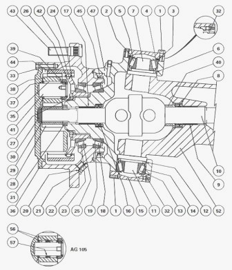
Remove the planet carrier. Remove the circlip (29) and the sun gear
(28). To avoid damaging the thread of the swivel housing (47), it is
recommended to correctly unlock the nut (27) and to loosen it using the
socket. Sling and remove the wheel hub (22). If necessary, extract
bearing cones (18) (25). Drive out the cups (19) (23). If the bearings
are to be reused, pair up the cones and cups. Check and clean the
components. Replace any defective parts.
Massey Ferguson 5445, 5455, 5460, 6460, 6470 - Assembling
bearing cones and cups
Reused cups (19) (23) and cones (18) (25). Install the previously paired
cups and cones to the respective machined shoulders on the wheel hub,
the swivel housing and the ring gear carrier.
New cups and cones - The bearing cups and cones must be of a special
class (width tolerance 0.1 mm instead of 0.2 mm). Bearing shimming is
determined according to the machined tolerances of the housing (47), hub
(22) and ring gear carrier (42). The parts listed above can be replaced
individually. To correctly guide the hub (22) onto the cassette seal
(45), fit the ring gear carrier (42). If the hub (22) does not rotate
freely after assembly, look for the component(s) that are causing the
problem. Lubricate the splines of the swivel housing (47). Degrease the
thread of the nut on the swivel housing. Lightly smear the nut (27) with
Loctite 270 or equivalent and tighten to a torque of 400-450 Nm. Lock
the nut in the housing groove by bending its collar, without breaking
it. Reinstall the sun gear (28) and the circlip (29). Reinstall the
planet carrier.
Replacing a wheel stud
Chock the rear wheels. Apply the hand brake. Raise the relevant side of
the tractor with a jack, position an axle stand and take off the front
wheel. Drive out the defective stud. Lightly smear the serrated area of
the new stud with Loctite 270 or equivalent and insert it using a bronze
drift and a suitable hammer. Reinstall the wheel. Remove the axle stand
and the jack. Tighten the nuts to a torque of 400 - 450 Nm.
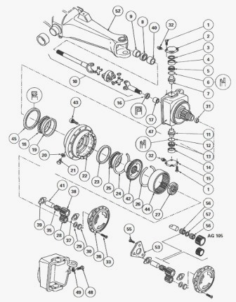
MF 5445, 5455, 5460, 6460, 6470 - Disassembling,
reassembling and shimming the swivel housing
Remove the planet carrier. Take off the sun gear and wheel hub. If
necessary, remove the seal (45) using a suitable puller or a makeshift
fitting. Remove the pin and the nut from the steering ball joint.
Extract the ball joint. Support the swivel housing (47) with a suitable
sling. Take out the screws (1), and remove the cover plate (15) and cup
(14). Extract the lower pivot pin (11). Repeat for the upper pivot pin
(7).
If required, extract the cones (5) (13) from the pivot pins. Cover the
splines of the universal joint shaft to avoid damaging the seal (16).
Remove the swivel housing (47). If necessary, take off the seal (16) and
drive out the ring (17). The ring is adhered with Loctite 270. If
necessary, remove the universal joint shaft. Take off the protective
ring (40), seal (8) and extract the ring (9). Check and clean the
components. Replace any defective parts. If removed, Install the ring
(9) and the seal (8) up against the shoulder of the housing (52).
Lubricate the seal (8). Reinstall the universal joint shaft. Insert a
guide via the filler hole to align the left-hand side of the shaft with
the differential. If removed, Install the ring (17) and the seal (16) up
against the shoulder of the swivel housing (47). Replace the seals (6)
(12). Turn the lips.
The steering stops are adjusted by turning the screws (48). Depending on
the required steering angle, refer to the following pic: Dimension X /
Steering angle: 77 mm / 35°, 63 mm / 40°, 34 mm / 50°.
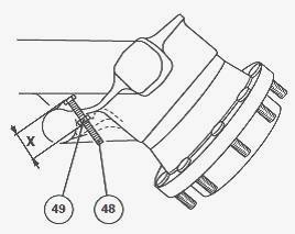
After adjustment, tighten nut (49). Install the bearing cones (5) (13)
onto their respective pins (7) (11). Reinstall the swivel housing (47).
Position the upper pin (7) to align the housing assembly with the
housing (52). Install the pin, ensuring that the lip of the seal (6) is
correctly positioned. Install the cup (4) and shims (3) removed when the
cover plate (2) was disassembled. Install and tighten the screws (1) in
a uniform and alternate manner. Install the lower pin (11) smeared with
Anti-Seize grease, checking that the lip of the seal (12) is correctly
positioned. Install the cup (14) and the cover plate (15). Install and
tighten the screws (1) to 115 - 140 Nm. Check that the pins (7) (11) are
in contact with the housing. After fitting the pins, temporarily take
out the shims (3). Refit the cover plate (2) and tighten the screws to
115 - 140 Nm. Check or carry out P1 shimming.
Shimming P1
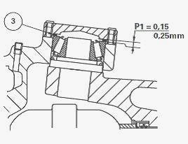
Use a dial gauge to measure the axial clearance by moving the swivel
housing vertically with a lever. Fill the clearance measured during the
previous step with a corresponding thickness of shims (3). To obtain P1,
add extra shims between 0.15 and 0.25 mm thick (0.15 to 0.25 is the
preload value). Remove screws (1) and cover plate (2). Install shims (3)
selected previously. Install the cover plate. Tighten the screws to a
torque of 115 - 140 Nm. Continue the reassembly procedure. Using a
grease gun, grease the bearings (13) (14) and (4) (5). Smear the rim of
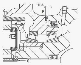
the seal (45) with Loctite 542 and oil the lips. Insert the seal using
tools. Tool must be screwed home. The seal (45) does not install up
against the shoulder of the housing; the ring determines its position.
Smear nut D and its mating face with graphite grease. The repositioning
dimension of the seal (45) in relation to face F is 11.5 mm.
Reinstall the steering ball joint. Tighten the nut to a torque of
115-130 Nm. Lock the nut using a new pin. Reassemble the wheel hub.
Reinstall the sun gear (28) and the circlip (29). Reinstall the planet
carrier.
Massey Ferguson 5445, 5455, 5460, 6460, 6470 - Removing
and reinstall the universal joint shaft
Remove the planet carrier. Take off the circlip (29), the sun gear (28)
and extract the steering ball joint. To remove the swivel housing (47)
and the wheel hub (22) assembly. Remove the universal joint shaft.
Disassembling the universal joint
Hold the external part (1) of the shaft in a vice Installed with soft
jaws. Remove the four circlips (3) from each end of the universal joint.
Using a plastic hammer, drive the central clevis (2) downwards until the
bearing sleeve projects from it. Secure the bearing sleeve in a vice and
strike the clevis to drive it out. Take off the opposite bearing sleeve
in the same way and remove the external part of the shaft. Turn the
shaft assembly 90°, then repeat steps to release the universal joint
from the shaft. Secure the inside section of the shaft in a vice.
Reassembling the universal joint
Clean and check the components. Replace the universal joint assembly,
including the spiders, seal rings, bearings, sleeves and circlips. Smear
the needle rollers with bearing grease and ensure that they all stay in
the sleeves. Position the universal joint spider (1) in the clevis and
push it as far outwards as possible so that the end of the spider acts
as a guide to Install the sleeve fitted with the needle rollers. Drive
in the sleeve (1) deep enough into the clevis while holding the spider
in order to fit the circlip. Install the other sleeves and spiders in
the same way.
Reinstall the universal joint shaft. Insert a guide through the filler
port of the axle housing (52) to align the left-hand side of the shaft
with the differential, and make sure it continues to protrude. Reinstall
the swivel housing and wheel hub assembly. Position the upper pin (7) to
align the housing assembly with the housing (52). Install the pin,
ensuring that the lip of the seal (6) is correctly positioned. Install
the cup (4), shims (3) and cover plate (2). Install and tighten the
screws (1) in a uniform and alternate manner to a torque of 115-140 Nm.
Install the pin (11) smeared with Anti-Seize grease, checking that the lip of the seal (12) is correctly positioned. Install the cup (14) and the cover plate (15). Install and tighten the screws (1) to 115-140 Nm. Check that the pins (7) (11) are in contact with the housing. Using a grease gun, grease the bearings (13) (14) and (4) (5). Reinstall the steering ball joint. Tighten the nut to a torque of 115-130 Nm. Lock the nut using a new pin. Remove the protective cover placed over the splines of the universal joint shaft. Reinstall the sun gear (28) and the circlip (29). Reinstall the planet carrier.
________________________________________________________________________________
________________________________________________________________________________
________________________________________________________________________________________
 SPECS
SPECS LOADERS
 MAINTENANCE
 PROBLEMS
________________________________________________________________________________________
________________________________________________________________________________________
| MF TRACTORS SPECIFICATIONS |
 130
130 133
133 145
145 155
155 158
158________________________________________________________________________________________
 165
165 175
175 185
185 188
188 230
230________________________________________________________________________________________
 254
254 254S
254S 284S
284S 294
294 353
353________________________________________________________________________________________
 290
290 362
362 375
375 390
390 398
398________________________________________________________________________________________
 399
399 590
590 690
690 1010
1010 1030
1030________________________________________________________________________________________
 1020
1020 1150
1150 2620
2620 2640
2640 2645
2645________________________________________________________________________________________
 1540
1540 1736
1736 2660
2660 3065
3065 3095
3095________________________________________________________________________________________
 3650
3650 3680
3680 4255
4255 4355
4355 4370
4370________________________________________________________________________________________
 3630
3630 3635
3635 4245
4245 4445
4445 4609
4609________________________________________________________________________________________
 4710
4710 5435
5435 5475
5475 5610
5610 5711
5711________________________________________________________________________________________
 6150
6150 6170
6170 6180
6180 6270
6270 6290
6290________________________________________________________________________________________
 6445
6445 6499
6499 6614
6614 6713
6713 7465
7465________________________________________________________________________________________
 7495
7495 7614
7614 7622
7622 7715
7715 7726
7726________________________________________________________________________________________
 8210
8210 8270
8270 8650
8650 8727
8727 GC1705
________________________________________________________________________________________
| MF FRONT END LOADERS |
 1464 Loader
 1466 Loader
 1040 Loader
 1070 Loader
 905 Loader
________________________________________________________________________________________
 906 Loader
 915 Loader
 916 Loader
 921 Loader
 926 Loader
________________________________________________________________________________________
 931 Loader
 933 Loader
 936 Loader
 938 Loader
 939 Loader
________________________________________________________________________________________
 940 Loader
 941 Loader
 945 Loader
 946 Loader
 948 Loader
________________________________________________________________________________________
 949 Loader
 950 Loader
 951 Loader
 955 Loader
 956 Loader
________________________________________________________________________________________
 958 Loader
 960 Loader
 961 Loader
 965 Loader
 966 Loader
________________________________________________________________________________________
 968 Loader
 975 Loader
 976 Loader
 978 Loader
 985 Loader
________________________________________________________________________________________
 FL.3114 X
 FL.3419 X
 FL.3522
 FL.3615
 FL.3619
________________________________________________________________________________________
 FL.3817
 FL.3819
 FL.3823
 FL.4018
 FL.4121
 916X Loader
 921X Loader
 926X Loader
 931X Loader
 936X Loader
________________________________________________________________________________________
 941X Loader
 946X Loader
 951X Loader
 956X Loader
 988 Loader
________________________________________________________________________________________
 FL.4125
 FL.4227
 FL.4124
 FL.4220
 FL.4323
________________________________________________________________________________________
 FL.4327
 FL.4621
 FL.4624
 FL.4628
 FL.5033
________________________________________________________________________________________
 DL95 Loader
 DL100 Loader
 DL120 Loader
 DL125 Loader
 DL130 Loader
________________________________________________________________________________________
 DL135 Loader
 DL250 Loader
 DL260 Loader
 L90 Loader
 L100 Loader
________________________________________________________________________________________
 L105E Loader
 L210 Loader
 1014 Loader
 1016 Loader
 1462 Loader
________________________________________________________________________________________
 1525 Loader
 1530 Loader
 232 Loader
 838 Loader
 848 Loader
________________________________________________________________________________________
 246 Loader
 1036 Loader
 1038 Loader
 1080 Loader
 856 Loader
________________________________________________________________________________________
| MF TRACTORS MAINTENANCE |
 1010
1010 1020
1020 1030
1030 1035
1035 1040
1040________________________________________________________________________________________
 1045
1045 1080
1080 1085
1085 1120
1120 1125
1125________________________________________________________________________________________
 1140
1140 1160
1160 1165
1165 1180
1180 1190
1190________________________________________________________________________________________
 1205
1205 1210
1210 1215
1215 1220
1220 1225
1225________________________________________________________________________________________
 1230
1230 1233
1233 1235
1235 1240
1240 1260
1260________________________________________________________________________________________
| MF TRACTORS TROUBLESHOOTING | ||||
| 1652 | 1749 | 2620 | 2725 | 2805 |
| 3050 | 3120 | 3640 | 3709 | 4245 |
| 4455 | 5320 | 5455 | 5613 | 6150 |
| 6280 | 6480 | 6615 | 7618 | 7720 |