
________________________________________________________________________________
Massey Ferguson 5455, 5460, 5465 - Brake piston
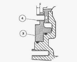
On MF 5435, 5445, 5455, 5460, 5465, 5470, 5475 tractors the brake pistons are housed in two lateral cavities of the rear axle housing, concentric with the mating face of each trumpet housing. They comprise a shouldered part and are guided by 3 centring pins force-fitted in the housing. Sealing is provided by two "O" rings fitted in the grooves of the rear axle housing. Each piston is controlled by a master cylinder topped by a tank whose level is kept constant by the residual oil flow from the 17 bar valve. Each piston acts directly on a friction disc with inserted hub, fitted to the trumpet housing input sun gear and a plate centred by pins bearing on the final drive ring gear.
When the brake is released, a self-adjusting mechanism ensures minimum
clearance between the piston and the brake disc and maintains a constant
pedal clearance. The brake discs are lubricated by a flow of oil. This
continuous flow from the linkage valve is directed to the brake discs
via a pipe and a restrictor union screwed onto the trumpet housing. The
oil circulating between the discs and the pistons lubricates the braking
surfaces when they are not in use and cools the brakes when they are
being used.
Massey Ferguson 5435, 5445, 5455, 5460, 5465,
5470, 5475 - Disassembly and reassembly brake piston
Brake piston disassembly
Remove the trumpet housing.
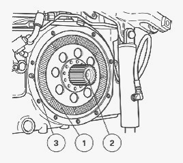
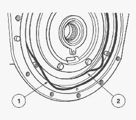
Remove the disc (1), the sun gear (2), and the centring pin (3). Remove
the brake plate (1) (inside the trumpet housing). Remove the screws (3)
using a makeshift socket.
Take the piston (1) out of the housing using a jet of compressed air
applied to the union (2). To facilitate access to the union (2), if
necessary, disconnect the 4-speed economy PTO control (if fitted) and
turn the union. Remove the "O" rings (1) and (2) on the housing and
discard them.
Brake piston reassembly
Check and clean the components. Replace any defective parts. To ensure
that the brake self-adjusting system operates correctly, it is essential
to centre the right and left-hand differential flanges using a makeshift
tool.
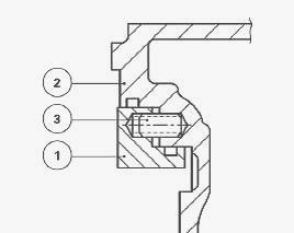
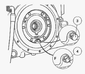
Install the piston (1) without seals in the housing (2) and check that
the piston slides freely in the bore of the housing and that it fits
smoothly onto the centring pins (3). Remove the piston after carrying
out this check. Install spring pins (4) about 8 mm from machined face
"F" of the piston (3). Install the new "O" rings (1) and (2) after
smearing them with a moderate quantity of miscible grease so that they
remain at the bottom of the groove.
Position the piston over the centring pins, then Install the piston in
place using a plastic hammer, striking alternate points around the rim.
Install the screws (3) after lightly smearing them with Loctite 241 and
tighten them to a torque of 10 Nm with a makeshift socket.
Massey Ferguson 5435, 5445, 5455, 5460, 5465,
5470, 5475 - brake piston sealing test
If work is carried out on the brake piston and "O" rings, it is
necessary to check for leaks. Check the condition of the supply union
fitted on the centre housing. Install a pressure gauge to the union.
Supply the system with compressed air at approx. 5 bar to ensure that
the piston and "O" rings are positioned correctly. Reduce the pressure
to 0.3 bar to carry out the test. Close off the pressure relief valve.
For one minute, no drop in pressure should be observed on the pressure
gauge. Remove the pressure gauge and reconnect the brake hose.
Reinstall the trumpet housing
Clean the mating faces on the housing and on the trumpet housing with a
non-greasy solvent. Apply a bead of silicon resistant to hydrocarbons
(Silicomet type) to the inside edge of the housing. Re Install the sun
gear (2), the disc (1), and the centring pin (3). Check that the disc
slides freely on the sun gear. Reinstall the trumpet housing. Bleed the
main brake system and trailer brake system (if fitted). Test: the
linkage, the braking by carrying out a road test. Check tightness:
between the trumpet housing and the rear axle housing, of the linkage
valve supply hose.
________________________________________________________________________________
________________________________________________________________________________
________________________________________________________________________________________
 SPECS
SPECS LOADERS
 MAINTENANCE
 PROBLEMS
________________________________________________________________________________________
________________________________________________________________________________________
| MF TRACTORS SPECIFICATIONS |
 130
130 133
133 145
145 155
155 158
158________________________________________________________________________________________
 165
165 175
175 185
185 188
188 230
230________________________________________________________________________________________
 254
254 254S
254S 284S
284S 294
294 353
353________________________________________________________________________________________
 290
290 362
362 375
375 390
390 398
398________________________________________________________________________________________
 399
399 590
590 690
690 1010
1010 1030
1030________________________________________________________________________________________
 1020
1020 1150
1150 2620
2620 2640
2640 2645
2645________________________________________________________________________________________
 1540
1540 1736
1736 2660
2660 3065
3065 3095
3095________________________________________________________________________________________
 3650
3650 3680
3680 4255
4255 4355
4355 4370
4370________________________________________________________________________________________
 3630
3630 3635
3635 4245
4245 4445
4445 4609
4609________________________________________________________________________________________
 4710
4710 5435
5435 5475
5475 5610
5610 5711
5711________________________________________________________________________________________
 6150
6150 6170
6170 6180
6180 6270
6270 6290
6290________________________________________________________________________________________
 6445
6445 6499
6499 6614
6614 6713
6713 7465
7465________________________________________________________________________________________
 7495
7495 7614
7614 7622
7622 7715
7715 7726
7726________________________________________________________________________________________
 8210
8210 8270
8270 8650
8650 8727
8727 GC1705
________________________________________________________________________________________
| MF FRONT END LOADERS |
 1464 Loader
 1466 Loader
 1040 Loader
 1070 Loader
 905 Loader
________________________________________________________________________________________
 906 Loader
 915 Loader
 916 Loader
 921 Loader
 926 Loader
________________________________________________________________________________________
 931 Loader
 933 Loader
 936 Loader
 938 Loader
 939 Loader
________________________________________________________________________________________
 940 Loader
 941 Loader
 945 Loader
 946 Loader
 948 Loader
________________________________________________________________________________________
 949 Loader
 950 Loader
 951 Loader
 955 Loader
 956 Loader
________________________________________________________________________________________
 958 Loader
 960 Loader
 961 Loader
 965 Loader
 966 Loader
________________________________________________________________________________________
 968 Loader
 975 Loader
 976 Loader
 978 Loader
 985 Loader
________________________________________________________________________________________
 FL.3114 X
 FL.3419 X
 FL.3522
 FL.3615
 FL.3619
________________________________________________________________________________________
 FL.3817
 FL.3819
 FL.3823
 FL.4018
 FL.4121
 916X Loader
 921X Loader
 926X Loader
 931X Loader
 936X Loader
________________________________________________________________________________________
 941X Loader
 946X Loader
 951X Loader
 956X Loader
 988 Loader
________________________________________________________________________________________
 FL.4125
 FL.4227
 FL.4124
 FL.4220
 FL.4323
________________________________________________________________________________________
 FL.4327
 FL.4621
 FL.4624
 FL.4628
 FL.5033
________________________________________________________________________________________
 DL95 Loader
 DL100 Loader
 DL120 Loader
 DL125 Loader
 DL130 Loader
________________________________________________________________________________________
 DL135 Loader
 DL250 Loader
 DL260 Loader
 L90 Loader
 L100 Loader
________________________________________________________________________________________
 L105E Loader
 L210 Loader
 1014 Loader
 1016 Loader
 1462 Loader
________________________________________________________________________________________
 1525 Loader
 1530 Loader
 232 Loader
 838 Loader
 848 Loader
________________________________________________________________________________________
 246 Loader
 1036 Loader
 1038 Loader
 1080 Loader
 856 Loader
________________________________________________________________________________________
| MF TRACTORS MAINTENANCE |
 1010
1010 1020
1020 1030
1030 1035
1035 1040
1040________________________________________________________________________________________
 1045
1045 1080
1080 1085
1085 1120
1120 1125
1125________________________________________________________________________________________
 1140
1140 1160
1160 1165
1165 1180
1180 1190
1190________________________________________________________________________________________
 1205
1205 1210
1210 1215
1215 1220
1220 1225
1225________________________________________________________________________________________
 1230
1230 1233
1233 1235
1235 1240
1240 1260
1260________________________________________________________________________________________
| MF TRACTORS TROUBLESHOOTING | ||||
| 1652 | 1749 | 2620 | 2725 | 2805 |
| 3050 | 3120 | 3640 | 3709 | 4245 |
| 4455 | 5320 | 5455 | 5613 | 6150 |
| 6280 | 6480 | 6615 | 7618 | 7720 |