
________________________________________________________________________________
Massey Ferguson 5455, 5460, 5465 - Rear axle differential lock
The left-hand flange contains the differential lock mechanism. The system consists of a piston and a mobile dog clutch splined with the left-hand trumpet housing input sun gear. The mobile dog clutch is moved by the piston which is supplied by the 17 bar hydraulic system via a solenoid valve fitted on the right-hand cover plate.
The piston moves and pushes against the mobile dog clutch, compressing
the spring. The teeth of the mobile dog clutch engage with a fixed dog
clutch that is attached to the differential unit. In this position, the
right and left-hand trumpet housing input sun gears turn at the same
speed. When the pressure is released, the mobile dog clutch is driven
back by the spring.
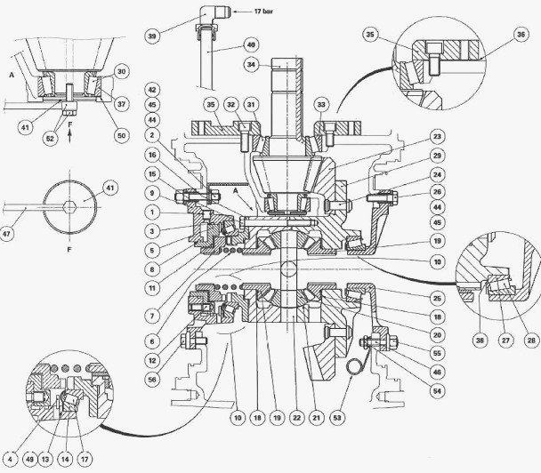
Parts list - (1) "O" ring (2) Stud (3) "O" ring (4)
Circlip (5) Piston (6) Spring (7) Mobile dog clutch (8) "O" ring (9)
Left-hand flange (10) Differential lock hydraulic assembly (11) Friction
washer (12) Finger (13) Deflector (14) Bearing cup (15) Screw (16) Fixed
dog clutch (17) Bearing cone (18) Washer (19) Sun gear (20) Planet gears
(21) Washer (22) Spider (23) Ring gear (24) Rivets (25) Right-hand
flange (26) Screw (27) Bearing cup (28) Bearing cone (29) Unit (30)
Bearing cone (31) Bearing cone (32) Screw (33) Bearing cup (34) Pinion
(35) Thrust plate (36) Shim(s) (37) Bearing cup (38) Shim(s) (39) Union
(40) Differential lock supply pipe (41) Lubrication plug (42) Clip nut
(differential support) (44) Washer (45) Locating ring (differential
support) (46) Stud (47) Pipe (48) Union (49) Shim(s) (50) Shim(s) (51)
Nut (securing the lubrication pipe) (52) Lubricating union (53) Spool
valve tank return pipe (54) Clip nut (55) Clip nut (differential
support) (56) Screw
MF 5435, 5445, 5455, 5460, 5465, 5470, 5475 -
Removing the left-hand flange and differential lock assembly
It is possible to carry out maintenance on the differential lock
hydraulic assembly (10) by removing only the left-hand trumpet housing.
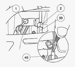
Remove the left-hand trumpet housing. Disconnect the supply pipe (2),
unscrew the union (39) and take out the pipe (40). If access to the
union (39) is difficult on tractors fitted with 4-speed economy PTO,
remove the control (1). Remove the brake piston. Purpose of the studs
(2) and (46). Stud (2): this helps to attach the left-hand flange (9).
it holds the lubrication pipe (47) for the pinion (34).
To reach the nut (3), remove the auxiliary spool valve support and work
through the resulting opening. If this operation has to be carried out
on a tractor fitted with 4-speed economy PTO, it is necessary to also
remove the hitch hook support and the PTO top cover plate located at the
rear of the tractor, the double gear and the control fork. Stud (46):
this attaches the right-hand flange (25).
It supports the return pipe (53) of the hydraulic spool valves. The two
studs (2) and (46) are fitted in the housing with a locking product
(Loctite 242 or equivalent). The nuts on either side are tightened like
the other screws holding the flanges, to a torque of 85-100 Nm. Remove
the flange (9), the locating ring (45), and if necessary, the friction
washer (11), the mobile dog clutch (7) and the spring (6).
Massey Ferguson 5435, 5445, 5455, 5460, 5465,
5470, 5475 - Disassembling and reassembling the differential lock
assembly
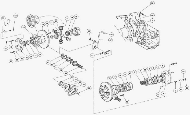
Differential lock disassembly
Take out cup (14), deflector (13) and shim (49) (if fitted). Mark the
deflector fitting direction and the location of the shim (49). Remove
the circlip (4). Take out the piston (5) using a jet of compressed air.
Remove the "O" rings (3) (8) (1). Unscrew the finger (12) (if
necessary).
Differential lock reassembly
Check the components and replace those that are defective. Clean finger
(12), smear it with Loctite 542, then Install it and tighten it on
flange (9). Smear the "O" rings (3) (8) with miscible grease ("Amber
Technical" or equivalent), and fit them correctly in the bottom of their
respective grooves. Using a plastic hammer, insert the piston (5) into
the flange (9) while respecting the location of the finger (12). Install
the circlip (4), the shim (49) (if necessary), and the deflector (13),
respecting its fitting direction, and the cup (14). The shim (49) (if
used) must be fitted between the flange (9) and the deflector (13).
MF 5435, 5445, 5455, 5460, 5465, 5470, 5475 -
Reinstall the left-hand flange and the differential lock assembly
Install the "O" ring (1). Assemble the washer (11), the mobile dog
clutch (7) and the spring (6). Reinstall the assembly in the left-hand
flange (9). Flange (9) fitting method.
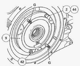
Screw two guide studs "G" (L = 60 mm approx.) onto the centre housing.
Check for the presence of the ring (45). Position the flange assembly
(9) turning it so that the oil passage is facing downwards. Install the
washer (44). Tighten alternately and uniformly the screw (56) and nut
(42) to a torque of 85-100 Nm. Install the pipe (40) and the union (39).
Sealing test
If maintenance has been carried out on the piston (5), seals (3) (8) or
flange (9), it is necessary to check the sealing of the assembly.
Install a pressure gauge that has been previously tested for tightness
to the supply union (39). Supply the system with compressed air at
approximately 5 bar to correctly place the piston and the "O" rings in
the left-hand flange (9). Reduce the pressure to 0.3 bar and carry out
the sealing test. Close the valve.
For approximately one minute, no drop in pressure should be observed on the pressure gauge. Disconnect the pressure gauge and connect the supply pipe (2). If removed, reconnect the 4-speed economy PTO control and set the control. Reinstall the brake piston and the left-hand trumpet housing. Start the engine. Check the sealing of the supply pipe (2) and the correct operation of the differential lock.
________________________________________________________________________________
________________________________________________________________________________
________________________________________________________________________________________
 SPECS
SPECS LOADERS
 MAINTENANCE
 PROBLEMS
________________________________________________________________________________________
________________________________________________________________________________________
| MF TRACTORS SPECIFICATIONS |
 130
130 133
133 145
145 155
155 158
158________________________________________________________________________________________
 165
165 175
175 185
185 188
188 230
230________________________________________________________________________________________
 254
254 254S
254S 284S
284S 294
294 353
353________________________________________________________________________________________
 290
290 362
362 375
375 390
390 398
398________________________________________________________________________________________
 399
399 590
590 690
690 1010
1010 1030
1030________________________________________________________________________________________
 1020
1020 1150
1150 2620
2620 2640
2640 2645
2645________________________________________________________________________________________
 1540
1540 1736
1736 2660
2660 3065
3065 3095
3095________________________________________________________________________________________
 3650
3650 3680
3680 4255
4255 4355
4355 4370
4370________________________________________________________________________________________
 3630
3630 3635
3635 4245
4245 4445
4445 4609
4609________________________________________________________________________________________
 4710
4710 5435
5435 5475
5475 5610
5610 5711
5711________________________________________________________________________________________
 6150
6150 6170
6170 6180
6180 6270
6270 6290
6290________________________________________________________________________________________
 6445
6445 6499
6499 6614
6614 6713
6713 7465
7465________________________________________________________________________________________
 7495
7495 7614
7614 7622
7622 7715
7715 7726
7726________________________________________________________________________________________
 8210
8210 8270
8270 8650
8650 8727
8727 GC1705
________________________________________________________________________________________
| MF FRONT END LOADERS |
 1464 Loader
 1466 Loader
 1040 Loader
 1070 Loader
 905 Loader
________________________________________________________________________________________
 906 Loader
 915 Loader
 916 Loader
 921 Loader
 926 Loader
________________________________________________________________________________________
 931 Loader
 933 Loader
 936 Loader
 938 Loader
 939 Loader
________________________________________________________________________________________
 940 Loader
 941 Loader
 945 Loader
 946 Loader
 948 Loader
________________________________________________________________________________________
 949 Loader
 950 Loader
 951 Loader
 955 Loader
 956 Loader
________________________________________________________________________________________
 958 Loader
 960 Loader
 961 Loader
 965 Loader
 966 Loader
________________________________________________________________________________________
 968 Loader
 975 Loader
 976 Loader
 978 Loader
 985 Loader
________________________________________________________________________________________
 FL.3114 X
 FL.3419 X
 FL.3522
 FL.3615
 FL.3619
________________________________________________________________________________________
 FL.3817
 FL.3819
 FL.3823
 FL.4018
 FL.4121
 916X Loader
 921X Loader
 926X Loader
 931X Loader
 936X Loader
________________________________________________________________________________________
 941X Loader
 946X Loader
 951X Loader
 956X Loader
 988 Loader
________________________________________________________________________________________
 FL.4125
 FL.4227
 FL.4124
 FL.4220
 FL.4323
________________________________________________________________________________________
 FL.4327
 FL.4621
 FL.4624
 FL.4628
 FL.5033
________________________________________________________________________________________
 DL95 Loader
 DL100 Loader
 DL120 Loader
 DL125 Loader
 DL130 Loader
________________________________________________________________________________________
 DL135 Loader
 DL250 Loader
 DL260 Loader
 L90 Loader
 L100 Loader
________________________________________________________________________________________
 L105E Loader
 L210 Loader
 1014 Loader
 1016 Loader
 1462 Loader
________________________________________________________________________________________
 1525 Loader
 1530 Loader
 232 Loader
 838 Loader
 848 Loader
________________________________________________________________________________________
 246 Loader
 1036 Loader
 1038 Loader
 1080 Loader
 856 Loader
________________________________________________________________________________________
| MF TRACTORS MAINTENANCE |
 1010
1010 1020
1020 1030
1030 1035
1035 1040
1040________________________________________________________________________________________
 1045
1045 1080
1080 1085
1085 1120
1120 1125
1125________________________________________________________________________________________
 1140
1140 1160
1160 1165
1165 1180
1180 1190
1190________________________________________________________________________________________
 1205
1205 1210
1210 1215
1215 1220
1220 1225
1225________________________________________________________________________________________
 1230
1230 1233
1233 1235
1235 1240
1240 1260
1260________________________________________________________________________________________
| MF TRACTORS TROUBLESHOOTING | ||||
| 1652 | 1749 | 2620 | 2725 | 2805 |
| 3050 | 3120 | 3640 | 3709 | 4245 |
| 4455 | 5320 | 5455 | 5613 | 6150 |
| 6280 | 6480 | 6615 | 7618 | 7720 |