
________________________________________________________________________________
Massey Ferguson 5465, 5470, 5475 - Hand brake unit and control
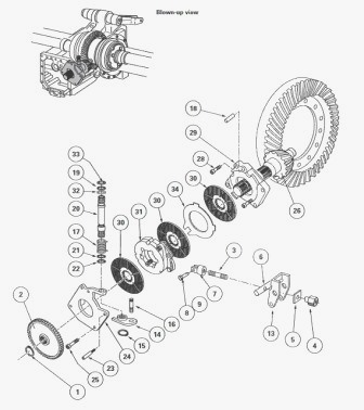
The hand brake assembly is fitted on the pinion. It consists of a
mechanism placed between three friction discs splined to the pinion. The
mechanism comprises two cast iron plates held by springs and separated
by ball bearings housed in rails. The three discs are fitted to the
pinion as follows: two discs separated by an intermediate plate between
the thrust plate (29) and the mechanism, disc between the mechanism and
the cover plate (24).
Hand brake operation
When the hand brake lever in the cab is pulled, the cam (14) is moved
via the pin (20). The cam pushes the rod (13) which causes the plates of
the mechanism (31) to rotate and move apart. The discs (30) are then
compressed between the moving plates (31), the intermediate plate (34),
the cover plate (24) and the thrust plate (29), preventing the pinion
from rotating. When the hand brake lever is released, the spring (17)
brings the cam (14) back to the rest position and the mechanism is
returned by its springs.
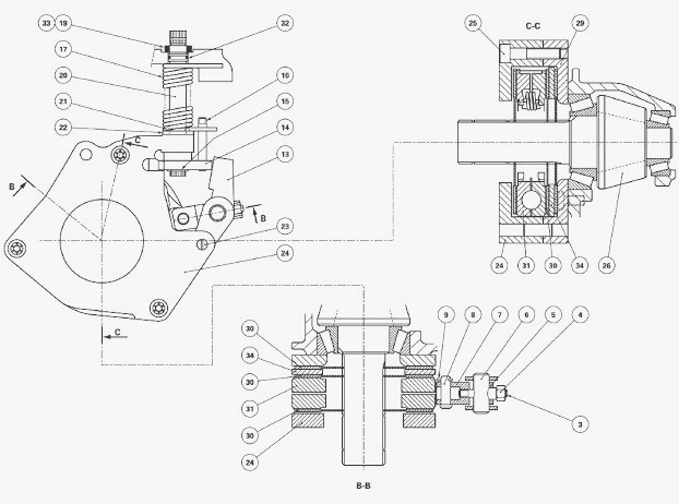
Parts list - (1) Circlip (2) Gear (3) Stud (4) Nut (5)
Gear plate (6) Pin (7) Clevis (8) Pin (9) Pin (10) Left-hand cover plate
(11) Plug (12) Seal (13) Rod (14) Cam (15) Circlip (16) Finger (17)
Spring (18) Centring pin (19) Seal (20) Control pin (21) Snap ring (22)
Washer (23) Finger (24) Cover plate (25) Screw (26) Pinion (27) Shim(s)
(28) Screw (29) Thrust plate (30) Discs (31) Mechanism (32) "O" ring
(33) Retaining ring (34) Intermediate plate
Massey Ferguson 5435, 5445, 5455, 5460, 5465,
5470, 5475 - Hand brake disassembly
Drain the rear axle housing. Chock: the front wheels of the tractor,
between the frame and the front axle. Raise the MF 5435, 5445, 5455,
5460, 5465, 5470, 5475 tractor using a jack. Place axle stands in
position. Remove the rear wheels. Remove the right and left-hand
hydraulic cover plates.
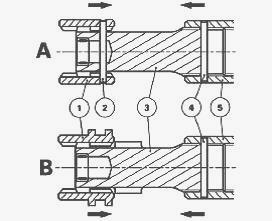
MF 5435, 5445, 5455, 5460, 5465, 5470, 5475 Tractor with no
creeper unit A
Drive out the double pins (2) (4) from the coupling sleeves (1) (5).
Slide the sleeves towards each other on the shaft (3) linking the pinion
(26) and the gearbox output shaft. Remove the shaft and sleeve assembly.
On MF 5435, 5445, 5455, 5460, 5465, 5470, 5475 4WD tractors: If the pins
are not accessible, disconnect the front axle shaft by sliding the rear
sleeve and manually turning the front axle clutch shaft to position the
shaft (3). Remove the circlip (1). Remove the gear (2) (if fitted).
MF 5435, 5445, 5455, 5460, 5465, 5470, 5475 Tractor with creeper
unit B
Remove the creeper gear fork and the sleeve assembly (connecting shaft
and coupler).
MF 5435, 5445, 5455, 5460, 5465, 5470, 5475 Tractors with or
without creeper unit
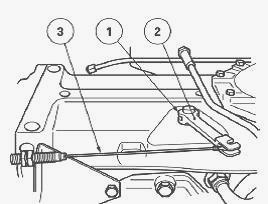
If necessary, remove the cab screws. Raise and chock the cab. Check the
space between the bonnet and the windscreen (if the space is too narrow,
remove the body). Disconnect the cable (3). Take out the pin (1) and
remove the control rod (2).
Remove the retaining ring (33) and remove the seal (19). Release the
spring (17) using a pair of pliers. Loosen the nut (4) to release the
rod (13) from the cam (14). Remove the circlip (15). Remove the cam (14)
with the finger (16). Remove the screw (25). Remove the cover plate (24)
and the control pin (20). Keep the mechanism (31) and the brake discs
(30) towards the rear. Extract the cover plate (24), tilting it to
disengage it from the pin (18), the finger (23) and the pinion (26) and
to release the pin (20) from the housing. Remove the spring (17) and the
washer (22). Remove the snap ring (21) (if necessary) on the control pin
(20). Remove the discs (30) and the mechanism (31).
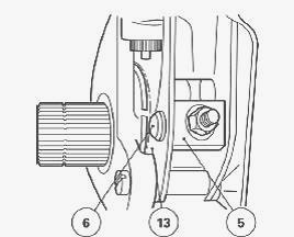
If replacing the mechanism - Unscrew the nut (4) and remove the plate
(5) and the pin (6). Take out the pin (9) and remove the pin (8) and the
clevis (7). The stud (3) is smeared with Loctite 270 and locked in the
clevis (7). If replacing the thrust plate (29) - Remove two
diametrically opposed screws (28) and screw in two guide studs (A). The
purpose of this operation is to hold the shims (27).
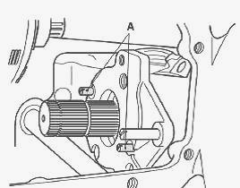
Unscrew the two remaining screws. Remove the thrust plate (29). Check
that the shims have all remained on the housing. The finger (16) smeared
with Loctite 270 is screwed onto the cam (14). The finger (23) smeared
with Loctite 270 is screwed onto the thrust plate. The centring pin (18)
is fitted home on the shoulder of the cover plate (24). Check and clean
the components. Replace any defective parts.
If replacing the thrust plate (29) - Reinstall the plate. Smear the two
screws (28) with Loctite 270 and then tighten them to a torque of 90-120
Nm. If replacing the mechanism - Reinstall the clevis (7) prepared with
the stud (3) and the pin (8). Reinstall the pin (9). Install the rod
(13) with its pin (6) on the stud (3) of the clevis. Reinstall the plate
(5) and screw on the nut (4). The plate (5) is rectangular. It must be
positioned horizontally so that the pin (6) Install correctly on the rod
(13).
Reinstall the discs (30), placing the mechanism (31) between them.
Insert the rod (13) on the finger (23). Check that the discs slide
freely on the shaft of the pinion (26). Install the snap ring (21) (if
removed) on the pin (20). Install the pin (20) in the cover plate (24)
with the washer (22), the spring (17) and the seal (32). Check that the
discs (30) and the mechanism (31) are correctly positioned. Install and
tighten the screws (25) to a torque of 90 - 120 Nm. Install the cam (14)
with its finger (16).
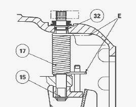
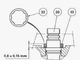
Position the circlip (15). Re-tension the spring (17), while positioning
its ends E as indicated. Lightly smear the pin (20) with AS 767
Anti-Seize grease or equivalent. Install the seal (19) on the housing
and compress it to 5.8 ± -0.15 mm using a retaining ring (33).
Reinstall the gear (2) (if fitted). Position the circlip (1). Depending
on the model: 1) with creeper unit - refit the sleeve assembly
(connecting shaft and coupler) and the creeper gear fork. Turn the
groove on the pinion sleeve towards the rear of the tractor. Replace the
pins. Adjust the forks. 2) without creeper unit - refit the sleeve
assembly (connecting shaft and coupler). Turn the groove on the pinion
sleeve towards the rear of the tractor. Replace the pins. Reinstall the
left-hand cover plate.
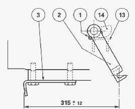
Position the rod (2) with the cam (14) in contact with the rod (13) to
obtain a distance of 315 mm ± 12 mm between the cable attachment axis
and the support (3). Install the pin (1).
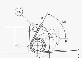
Adjust the mechanism (31) with the adjustment nut, so that the cam
displacement from rest position "a" to maximum position "b" is 60°. The
adjustment nut (4) is accessed via the plug port (3) on the left-hand
cover plate. Reconnect the control. Adjust the hand brake control
reverse. Reinstall the right-hand hydraulic cover plate. Raise the
tractor using a jack. Install the wheels.
Remove the axle stands and the jack. Tighten the wheels to a torque of
400-450 Nm. Remove the chocks at the front of the tractor between the
frame and the front axle. Top up the rear axle housing oil level. Check
the operation of the electrical circuits, the low pressure switch, the
solenoid valves and the blockage indicator. Check the operation of the
linkage and the hand brake. Check the tightness of the mating faces,
cover plates and hydraulic unions.
Massey Ferguson 5435, 5445, 5455, 5460, 5465,
5470, 5475 - Assembling and adjusting the hand brake control
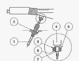
Introduce the cable (1) from below towards the cab interior and fasten
with the clip (2). Fix the clevis (7) on the brake lever (4) with the
pin (5), the washer (6) and the pin (3). Check that the cable is not
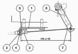
pinched. Install the sheath end (2) in the attachment support (1).
Attach the end of the cable (7) to the lever (6). Place the hand brake
lever in the released position. Make essential adjustments to obtain a
distance of 315 mm ± 12 mm between the nut (5) and the centreline of the
cable end (7). Tighten the nut (3) on the washer (4).
Check the operation of the control. Tighten the lever. Initial brake
travel should be approximately 8 notches. The indicator light on the
instrument panel should come on and the buzzer should sound if a gear is
engaged. Release the lever. The control should return freely to the rest
position. In this position, the buzzer stops and the indicator light on
the instrument panel should go out.
________________________________________________________________________________
________________________________________________________________________________
________________________________________________________________________________________
 SPECS
SPECS LOADERS
 MAINTENANCE
 PROBLEMS
________________________________________________________________________________________
________________________________________________________________________________________
| MF TRACTORS SPECIFICATIONS |
 130
130 133
133 145
145 155
155 158
158________________________________________________________________________________________
 165
165 175
175 185
185 188
188 230
230________________________________________________________________________________________
 254
254 254S
254S 284S
284S 294
294 353
353________________________________________________________________________________________
 290
290 362
362 375
375 390
390 398
398________________________________________________________________________________________
 399
399 590
590 690
690 1010
1010 1030
1030________________________________________________________________________________________
 1020
1020 1150
1150 2620
2620 2640
2640 2645
2645________________________________________________________________________________________
 1540
1540 1736
1736 2660
2660 3065
3065 3095
3095________________________________________________________________________________________
 3650
3650 3680
3680 4255
4255 4355
4355 4370
4370________________________________________________________________________________________
 3630
3630 3635
3635 4245
4245 4445
4445 4609
4609________________________________________________________________________________________
 4710
4710 5435
5435 5475
5475 5610
5610 5711
5711________________________________________________________________________________________
 6150
6150 6170
6170 6180
6180 6270
6270 6290
6290________________________________________________________________________________________
 6445
6445 6499
6499 6614
6614 6713
6713 7465
7465________________________________________________________________________________________
 7495
7495 7614
7614 7622
7622 7715
7715 7726
7726________________________________________________________________________________________
 8210
8210 8270
8270 8650
8650 8727
8727 GC1705
________________________________________________________________________________________
| MF FRONT END LOADERS |
 1464 Loader
 1466 Loader
 1040 Loader
 1070 Loader
 905 Loader
________________________________________________________________________________________
 906 Loader
 915 Loader
 916 Loader
 921 Loader
 926 Loader
________________________________________________________________________________________
 931 Loader
 933 Loader
 936 Loader
 938 Loader
 939 Loader
________________________________________________________________________________________
 940 Loader
 941 Loader
 945 Loader
 946 Loader
 948 Loader
________________________________________________________________________________________
 949 Loader
 950 Loader
 951 Loader
 955 Loader
 956 Loader
________________________________________________________________________________________
 958 Loader
 960 Loader
 961 Loader
 965 Loader
 966 Loader
________________________________________________________________________________________
 968 Loader
 975 Loader
 976 Loader
 978 Loader
 985 Loader
________________________________________________________________________________________
 FL.3114 X
 FL.3419 X
 FL.3522
 FL.3615
 FL.3619
________________________________________________________________________________________
 FL.3817
 FL.3819
 FL.3823
 FL.4018
 FL.4121
 916X Loader
 921X Loader
 926X Loader
 931X Loader
 936X Loader
________________________________________________________________________________________
 941X Loader
 946X Loader
 951X Loader
 956X Loader
 988 Loader
________________________________________________________________________________________
 FL.4125
 FL.4227
 FL.4124
 FL.4220
 FL.4323
________________________________________________________________________________________
 FL.4327
 FL.4621
 FL.4624
 FL.4628
 FL.5033
________________________________________________________________________________________
 DL95 Loader
 DL100 Loader
 DL120 Loader
 DL125 Loader
 DL130 Loader
________________________________________________________________________________________
 DL135 Loader
 DL250 Loader
 DL260 Loader
 L90 Loader
 L100 Loader
________________________________________________________________________________________
 L105E Loader
 L210 Loader
 1014 Loader
 1016 Loader
 1462 Loader
________________________________________________________________________________________
 1525 Loader
 1530 Loader
 232 Loader
 838 Loader
 848 Loader
________________________________________________________________________________________
 246 Loader
 1036 Loader
 1038 Loader
 1080 Loader
 856 Loader
________________________________________________________________________________________
| MF TRACTORS MAINTENANCE |
 1010
1010 1020
1020 1030
1030 1035
1035 1040
1040________________________________________________________________________________________
 1045
1045 1080
1080 1085
1085 1120
1120 1125
1125________________________________________________________________________________________
 1140
1140 1160
1160 1165
1165 1180
1180 1190
1190________________________________________________________________________________________
 1205
1205 1210
1210 1215
1215 1220
1220 1225
1225________________________________________________________________________________________
 1230
1230 1233
1233 1235
1235 1240
1240 1260
1260________________________________________________________________________________________
| MF TRACTORS TROUBLESHOOTING | ||||
| 1652 | 1749 | 2620 | 2725 | 2805 |
| 3050 | 3120 | 3640 | 3709 | 4245 |
| 4455 | 5320 | 5455 | 5613 | 6150 |
| 6280 | 6480 | 6615 | 7618 | 7720 |