
________________________________________________________________________________
Massey Ferguson 5445, 5455, 5465 - Hitch and linkage
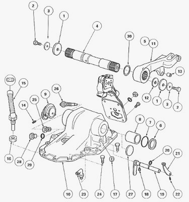
The linkage cover plate is fitted on the upper face of the rear axle housing. Via two rings, it supports the shaft (4), which has the two linkage arms (5) (11) splined to it. A cam (9), screwed on the shaft, inside the cover plate, shows the different positions taken by the linkage arms. This position information is recorded and sent by a sensor (26) to the electronic linkage controller.
To ensure a correct operational clearance between the linkage arms and
the cover plate, the shims (12) are fitted on the left-hand end of the
shaft. Two friction washers (30) prevent the arms coming into direct
contact with the cover plate. The rear face of the linkage cover plate
supports the auxiliary spool valves. The forward speed sensor (15) is
screwed to the front of the cover plate, which also supports the 4-speed
PTO control rod (21) (if fitted).
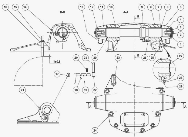
Parts list - (1) Washer (2) Screw (3) Lock washer (4)
Linkage shaft (5) Right-hand linkage arm (6) Nylon ring (7) "O" ring (8)
Ring (9) Cam (10) Linkage cover plate (11) Left-hand linkage arm (12)
Shim(s) (13) Ring (14) Set screw (15) Forward speed sensor (16) Nut (17)
Cup plug (2-speed PTO) (18) Screw (4-speed PTO) (19) Control finger
(4-speed PTO) (20) "O" ring (4-speed PTO) (21) Rod (4-speed PTO) (22)
Screw (4-speed PTO) (23) Elbow union (24) Screw (25) Nut (26) Position
sensor (27) Cup plug (version without linkage) (28) Threaded plug
(version without linkage) (29) Seal (30) Friction washers
Removal
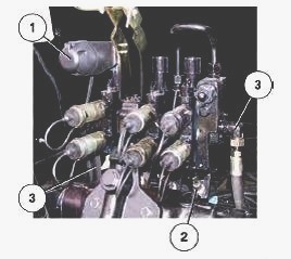
Remove: trailer electrical connector (1); spool valve control cables
(2); hydraulic unions connected to the spool valves (3); trailer brake
connector and its support, by undoing the unions at both ends; supply
pipes for the lift rams.
Disconnect: forward speed sensor (15) harness; position sensor (26)
harness; PTO control cable (4-speed PTO, if fitted). Remove the four
screws from the spool valve support. Remove the spool valve support with
the spool valves. Remove the upper pins from the rams and lift rods.
Remove the screws (24) from the linkage cover plate (10). Sling the
cover plate and remove it.
Disassembly
Place the cover plate on a workbench. Remove the elbow union (23).
Unscrew the nut (16) and remove the forward speed sensor (15). Unscrew
the nut (25) and remove the position sensor (26).
For MF 5435, 5445, 5455, 5460, 5465, 5470, 5475 tractors fitted
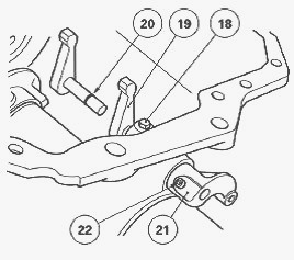
with 4-speed economy PTO - Loosen the Allen screw (22) of the
rod (21). Remove the screw (18). Remove the control finger (19). Remove
the "O" ring (20). Unlock the screws (2) for the linkage arms. Loosen
the screws. Remove the washers (1). Remove the shims (12). Remove the
linkage arms (5) (11) and the washers (30). Remove the nylon rings (6)
and the "O" rings (7). Remove the set screws (14) from the cam (9).
Extract the linkage shaft (4) from the cover plate. Remove the cam (9).
Remove the rings (8). Remove the cup plug (17) (2-speed PTO).
Reassembly
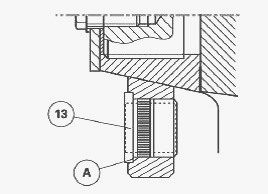
Fit the rings (13) up against the face "A".
Check and clean the components. Replace any defective parts. Clean the
mating faces of the linkage cover plate and of the spool valve support.
Fit the rings (8) in the cover plate. Fit the plug (17) smeared with
Loctite 542 level with the cover plate (2-speed PTO). Fit the linkage
shaft (4) and the cam (9) in the cover plate. Ensure that the fitting
direction of the shaft and the position of the cam are correct.

Tighten the set screws (14) smeared with Loctite 241 to a torque of 5
Nm. Protect the shaft splines. Lubricate the "O" rings before fitting.
Grease the splines of the shaft (4) (with Anti-Seize Grease or
equivalent). Fit the linkage arm (5) (sensor side), the washer (1), the
lock washer (3) and the screw (2). Grease the face of the cover plate
(with Anti-Seize Grease or equivalent) before fitting the arm. Tighten
the screw (2) to a torque of 360-470 Nm. If work has been done without
the need to carry out the shimming J1 (e.g. replacement of seals) it is
essential to fit the shims (12) at the left-hand end of the shaft
(factory fitting) to preserve the correct positioning of the cam and to
avoid having to adjust the sensor (26).
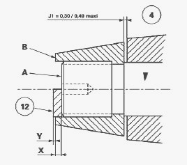
Carry out shimming of the shaft (4) to obtain the clearance: J1 = 0.10
to 0.20 maximum. Fit the arm (11), the washer (1) and the screw (2).
Tighten the screw to position the linkage arms (5) and (11) correctly on
the shaft. Measure the distance between face "A" of the shaft and face
"B" of the arm using a depth gauge. By measuring dimension "X",
determine the thickness of shims "Y" needed to obtain: J1 = 0.10 to 0.20
maximum, Y = X + J1. Fit the shims (12) selected previously, the washer
(1), the lock washer (3) and the screw (2). Tighten the screw (2) to a
torque of 360-470 Nm.
For MF 5435, 5445, 5455, 5460, 5465, 5470, 5475 tractors fitted
with a 4-speed PTO - Refit the finger (19). Fit the "O" ring
(20) from the external side of the cover plate. Smear the screws (18)
(22) with Loctite 241 and tighten. Check that the control functions
smoothly. Fit the elbow union (23).
Reinstall
Clean the mating face of the cover plate on the rear axle housing. Smear
the mating face with a sealing product (Master Joint 510 Loctite or
equivalent). Sling the cover plate and refit it. When refitting the
cover plate, check that the differential lock supply pipe and the
4-speed PTO control finger engage properly in their respective
positions. Fit the PTO control cable support (depending on option) and
fit the screws (24) for the cover plate (10).
Tighten to the following torque: screws D12 = 72-96 Nm, screws D16 =
160-200 Nm. Refit the upper pins for the lift rams. Refit the trailer
brake valve support if fitted. Retighten the pipe at both ends. Refit:
differential lock supply pipe on the union (23); control cable (21)
(4-speed PTO, if fitted). Fit the forward speed sensor (15) with Loctite
577 Sensor Sealing or equivalent. Screw home the speed sensor without
forcing it until it comes into contact with the differential ring gear.
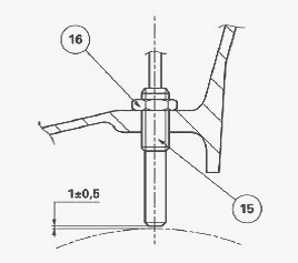
Unscrew the sensor 3/4 of a turn to obtain a clearance of approx. 1 mm
between the sensor and the ring gear. Tighten the nut (16) to a maximum
torque of 5 Nm. Connect the sensor harness. Secure the harness with a
retainer. Clean the mating face of the spool valve support cover plate.
Smear the mating face of the spool valve support cover plate with a
sealing product (Master Joint 510 Loctite or equivalent). Refit the
spool valve support. Refit the 4 screws for the spool valve support
after smearing their threads with Loctite 510. Tighten the screws to a
torque of 50-70 Nm. Refit the parts that were removed during step.
Massey Ferguson 5435, 5445, 5455, 5460, 5465,
5470, 5475 - Adjust the PTO control (4-speed)
Smear the thread of the position sensor (26) with a sealing product
(Hylomar or equivalent), then screw the sensor in a few turns. Start the
engine. Using the external controls, ensure that the linkage arms are in
the raised position (continuous pumping). Stop the engine. Screw in the
sensor (without forcing it) up against the cam (9). Connect the sensor
to the female connector of a makeshift harness. Connect the other test
harness connector to the tractor harness. Connect terminals 1 and 2 to a
multimeter. Start the engine. Lower the hitch by 3 to 5 cm, measured
between the hook and ground.
Unscrew the sensor to obtain a voltage of between 6.92 and 6.96 volts.
Reconnect the tractor harness. Stop the engine. Tighten the nut (25) to
a torque of 25 Nm using the makeshift wrench. Check tightness: of the
mating faces of the cover plate and the spool valve support; of the
hydraulic unions. Version without linkage - The ports of the shaft (4)
are plugged with the cup plugs (27) sealed with Loctite 542. The
position sensor (26) is replaced by a threaded plug fitted with a seal
(29).
MF 5435, 5445, 5455, 5460, 5465, 5470, 5475 -
Rear hitch
The hitch comprises several components, depending on option and country:
top link with a ball joint or hitch; two lower bars with ball joints,
automatic hooks or telescopic end fittings (depending on version); two
levelling units; two tube type stabilisers; a multi-hole drawbar.
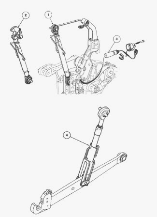
Top link: (1) top link with ball joint; (2) top link with hook; (3)
draft sensor. Levelling unit (4).
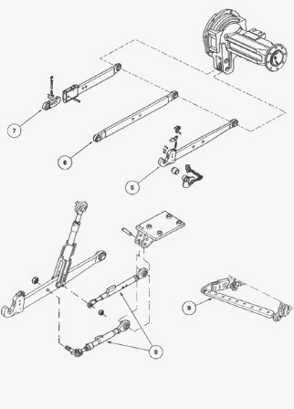
Lower links: (5) lower link with hook; (6) lower link with fixed ball
joint; (7) telescopic lower link; Telescopic stabiliser (8); Multi-hole
drawbar (9).
Massey Ferguson 5435, 5445, 5455, 5460, 5465,
5470, 5475 - Disassembling and reassembling a lift ram
Run the engine and lower the lower links to their maximum using the
tractor's electronic system. Disconnect the supply hose. Remove the ram
and drain its oil.
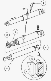
Disassembly
Remove the elbow union (1) fitted with its "O" ring. Pull the rod from
the ram (5) until the snap ring (4) appears in port O of the union.
Insert a screwdriver in this port and offset the snap ring into the
adjacent V-shaped groove of the rod while turning the rod at the same
time. Remove the rod and the snap ring (4). Drive out the wiper seal (2)
and the seal (3) (always discard these three parts).
Reassembly
Dry off all the components using a jet of compressed air. Lubricate the
assemblies with clean transmission oil. Assemble the ram. Lubricate the
upper and lower pins of the ram with "Anti-Seize" grease and refit the
ram. Reconnect the supply hose. Run the engine. Using the linkage
electronic controller, raise and lower the linkage arms to their maximum
positions several times. Check that the hitch operates correctly and
that there is no leakage of oil around the rim of the ram.
________________________________________________________________________________
________________________________________________________________________________
________________________________________________________________________________________
 SPECS
SPECS LOADERS
 MAINTENANCE
 PROBLEMS
________________________________________________________________________________________
________________________________________________________________________________________
| MF TRACTORS SPECIFICATIONS |
 130
130 133
133 145
145 155
155 158
158________________________________________________________________________________________
 165
165 175
175 185
185 188
188 230
230________________________________________________________________________________________
 254
254 254S
254S 284S
284S 294
294 353
353________________________________________________________________________________________
 290
290 362
362 375
375 390
390 398
398________________________________________________________________________________________
 399
399 590
590 690
690 1010
1010 1030
1030________________________________________________________________________________________
 1020
1020 1150
1150 2620
2620 2640
2640 2645
2645________________________________________________________________________________________
 1540
1540 1736
1736 2660
2660 3065
3065 3095
3095________________________________________________________________________________________
 3650
3650 3680
3680 4255
4255 4355
4355 4370
4370________________________________________________________________________________________
 3630
3630 3635
3635 4245
4245 4445
4445 4609
4609________________________________________________________________________________________
 4710
4710 5435
5435 5475
5475 5610
5610 5711
5711________________________________________________________________________________________
 6150
6150 6170
6170 6180
6180 6270
6270 6290
6290________________________________________________________________________________________
 6445
6445 6499
6499 6614
6614 6713
6713 7465
7465________________________________________________________________________________________
 7495
7495 7614
7614 7622
7622 7715
7715 7726
7726________________________________________________________________________________________
 8210
8210 8270
8270 8650
8650 8727
8727 GC1705
________________________________________________________________________________________
| MF FRONT END LOADERS |
 1464 Loader
 1466 Loader
 1040 Loader
 1070 Loader
 905 Loader
________________________________________________________________________________________
 906 Loader
 915 Loader
 916 Loader
 921 Loader
 926 Loader
________________________________________________________________________________________
 931 Loader
 933 Loader
 936 Loader
 938 Loader
 939 Loader
________________________________________________________________________________________
 940 Loader
 941 Loader
 945 Loader
 946 Loader
 948 Loader
________________________________________________________________________________________
 949 Loader
 950 Loader
 951 Loader
 955 Loader
 956 Loader
________________________________________________________________________________________
 958 Loader
 960 Loader
 961 Loader
 965 Loader
 966 Loader
________________________________________________________________________________________
 968 Loader
 975 Loader
 976 Loader
 978 Loader
 985 Loader
________________________________________________________________________________________
 FL.3114 X
 FL.3419 X
 FL.3522
 FL.3615
 FL.3619
________________________________________________________________________________________
 FL.3817
 FL.3819
 FL.3823
 FL.4018
 FL.4121
 916X Loader
 921X Loader
 926X Loader
 931X Loader
 936X Loader
________________________________________________________________________________________
 941X Loader
 946X Loader
 951X Loader
 956X Loader
 988 Loader
________________________________________________________________________________________
 FL.4125
 FL.4227
 FL.4124
 FL.4220
 FL.4323
________________________________________________________________________________________
 FL.4327
 FL.4621
 FL.4624
 FL.4628
 FL.5033
________________________________________________________________________________________
 DL95 Loader
 DL100 Loader
 DL120 Loader
 DL125 Loader
 DL130 Loader
________________________________________________________________________________________
 DL135 Loader
 DL250 Loader
 DL260 Loader
 L90 Loader
 L100 Loader
________________________________________________________________________________________
 L105E Loader
 L210 Loader
 1014 Loader
 1016 Loader
 1462 Loader
________________________________________________________________________________________
 1525 Loader
 1530 Loader
 232 Loader
 838 Loader
 848 Loader
________________________________________________________________________________________
 246 Loader
 1036 Loader
 1038 Loader
 1080 Loader
 856 Loader
________________________________________________________________________________________
| MF TRACTORS MAINTENANCE |
 1010
1010 1020
1020 1030
1030 1035
1035 1040
1040________________________________________________________________________________________
 1045
1045 1080
1080 1085
1085 1120
1120 1125
1125________________________________________________________________________________________
 1140
1140 1160
1160 1165
1165 1180
1180 1190
1190________________________________________________________________________________________
 1205
1205 1210
1210 1215
1215 1220
1220 1225
1225________________________________________________________________________________________
 1230
1230 1233
1233 1235
1235 1240
1240 1260
1260________________________________________________________________________________________
| MF TRACTORS TROUBLESHOOTING | ||||
| 1652 | 1749 | 2620 | 2725 | 2805 |
| 3050 | 3120 | 3640 | 3709 | 4245 |
| 4455 | 5320 | 5455 | 5613 | 6150 |
| 6280 | 6480 | 6615 | 7618 | 7720 |