
________________________________________________________________________________
Massey Ferguson 5445, 5455, 5465 - Rear axle trumpet housings
The trumpet housings support the right and left-hand axle shafts and
contain the final drive units that transmit the rotation from the
differential assembly. Both trumpet housings are symmetrical and fitted
on either side of the centre housing.
MF 5435, 5445, 5455, 5460, 5465, 5470, 5475 -
Trumpet housings construction
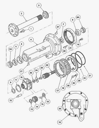
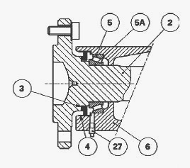
The axle shaft (2) is supported by two opposing tapered roller bearings
(5) (8). External sealing is ensured by a three-lipped seal (3) and
internal sealing is provided by a single lip seal (7). The three-gear
final drive unit (14) planet carrier assembly (10) is integral in
rotation with the shaft (2) via splines. The Normal Duty trumpet housing
planet gears have a single row of needle rollers (15). The internal
faces of the planet carrier (10) are rough cast and therefore require
adjustment using friction shims (13).
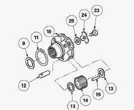
Shims (25) placed at the end of the shaft are used to preload the
tapered roller bearings. The shaft (2) and the planet carrier (10) are
held in place by the washer (24) and the screw (23). The final drive
ring gear (21) is force fitted into the trumpet housing and held in
place by the three screws (16). It has three pins (20) ensuring centring
of the brake plate (17). Differential rotation is transmitted to the
planet gears of the final drive via a sun gear shaft (22) on the teeth
of which the brake disc (18) is fitted. The brake discs are lubricated
by a continuous flow of oil from the linkage valve.
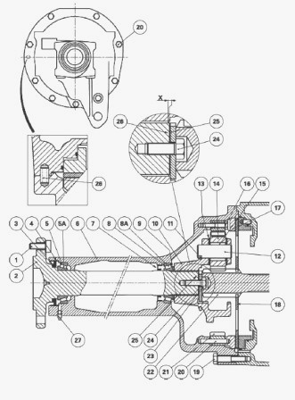
Parts list - (1) Wheel stud (2) Axle shaft (3)
Three-lipped seal (4) Seal cage (5) Bearing cup (5A) Bearing cone (6)
Trumpet housing (7) Seal (8) Bearing cup (8A) Bearing cone (9) Tab
washer (10) Planet carrier (11) Snap ring (12) Planet gear pin (13)
Friction shim(s) (14) Planet gears (15) Needle rollers (16) Screw (17)
Brake plate (18) Brake disc (19) Screw (20) Pin (21) Final drive ring
gear (22) Sun gear (23) Screw (24) Washer (25) Shim(s) (26) Pin (27)
Plug
Massey Ferguson 5435, 5445, 5455, 5460, 5465,
5470, 5475 - Trumpet housing assembly
Removal
Immobilise the tractor. Apply the hand brake. Chock between the frame
and the front axle. Drain the rear axle. Using a trolley jack, raise the
relevant side of the tractor. Place an axle stand in position. Remove
the wheel. Remove the stabilising support. Disconnect the hose (1) or
(3) and the brake lubrication pipe(s). Remove cab screws A.
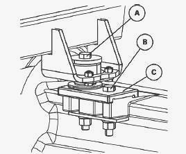
Raise the cab sufficiently to allow the trumpet housing to be removed
(chock the cab). Check the gap between the bonnet and the windscreen
(remove the body if necessary). If replacing the trumpet housing, remove
the supports C by removing the screws B. Underneath the trumpet housing,
position a suitable support on a trolley jack. For the left-hand trumpet
housing, disconnect the supply hose from the linkage valve (plug the
channels). Loosen the screws (19).
With the help of an operator and in compliance with the safety
regulations, separate the trumpet housing from the rear axle housing.
Remove: brake disc (18), sun gear (22), centring pin (26). Remove the
brake plate (17).
Reinstall
Clean the mating faces on the housing and on the trumpet housing with a
non-greasy solvent. Apply a bead of silicon resistant to hydrocarbons
(Silicomet type) to the inside edge of the housing. Check that the disc
(18) slides freely on the sun gear (22).
Reinstall the centring pin (26), the sun gear (22) and the brake disc
(18). Screw two diametrically opposed guide studs onto the housing.
Reinstall the brake plate (17) in the trumpet housing. In order to hold
the plate in place, apply three spots of miscible grease to the face of
the ring gear (21). Couple the trumpet housing to the rear axle,
following the safety procedures used during its removal. Turn the shaft
(2) to engage the sun gear (22) in the planet gears.
Clean the screws (19) and smear them with Plastex, Hylomar or an
equivalent sealing paste. Install and tighten the screws (19) to a
torque of 170-210 Nm. Install the cab screws. Reinstall the other
removed parts. Top up the oil level in the rear axle. Install the wheel.
Tighten to a torque of 400-450 Nm. Remove the axle stand. Test the
linkage and the brake system. Check tightness: between the trumpet
housing and the rear axle housing, of the linkage valve supply hose, of
the brake lubrication pipes.
MF 5435, 5445, 5455, 5460, 5465, 5470, 5475 -
Rear axle planet carrier
Disassembly
Remove the trumpet housing. Remove the screw (23). Take off the
retaining washer (24) and the shim(s) (25). Remove the planet carrier
(10).
Open the snap ring (11). Using a hammer, tap gently on the three pins
(12). Take out the three pins (12) and the snap ring (11). Remove the
three planet gears (14), the needle rollers (15) and the shims (13).
Reassembly
Clean the planet carrier (10), the pins (12) and the planet gears (14).
Check the parts. Smear the needle rollers with miscible grease. Install
a row of needle rollers in each planet gear. Shim the planet gears. The
shims (13) are available in three different thicknesses. Install the
planet gears (14) with the shims (13) of medium thickness on either side
of the planet gear. Engage the three pins (12).
Use a set of shims to determine a thickness of shims (13) to fit to
obtain an axial clearance of between 0.15 and 0.55 mm on each planet
gear. Pull gently on the three pins, and Install the shims (13). Push
back the three pins and the snap ring (11). Open the snap ring (11). Tap
gently on the three pins so that the snap ring Install into the groove
of the planet carrier. Ensure that the tab washer (9) is present.
Reinstall the planet carrier. Install shims to obtain the required
preload. Reinstall the trumpet housing.
Bearings and seals
Disassembly
Remove the trumpet housing from the rear axle housing. Remove the planet
carrier. Remove: tab washer (9); cone (8A) (free fitted on the shaft).
Take the shaft (2) out of the trumpet housing. Extract the cone (5A).
Drive out the lip seal (3). Using a puller, take out: cup (5); cage (4)
of the seal (3); cup (8). Drive out the seal (7).
Reassembly
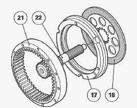
The ring gear (21) is force fitted in the trumpet housing (6). It is
centred by the three pins (20) (Loctite 638) and secured by the screws
(16). Tightening torque 79-90 Nm (Loctite 242). Clean the seal mating
faces and the location of cups and cones inside the trumpet housing and
on the shaft. The seal, cup and cone mating faces should be free of
burrs and dents. Smear the external surface of the seal (7) with Loctite
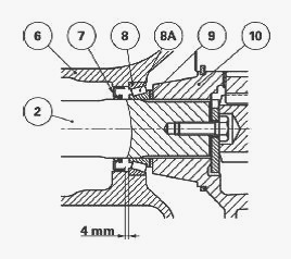
542 (metal cage). Replacing the seal (7): Without replacement of the
shaft 2): So that the seal lip does not rest in the same place on the
shaft, fit the seal 4 mm from the shoulder of the cup (8).
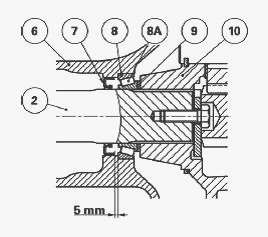
With replacement of the shaft (2): Position the seal 5 mm from the
shoulder of the cup (8).
Lubricate the cups (8) (5) and Install them home against the shoulder.
Install the cage (4) home against the shoulder. Install the three-lipped
seal (3) home against the shoulder of the shaft. Lubricate the shaft (2)
and Install the cone (5A) against the shoulder. Moderately grease the
cone (5A) and the lips of seals (3) (7) (using BP Agricharge grease or
equivalent). Protect the splines of the shaft (2) and insert it into the
trumpet housing. The lips of the seal (3) must be facing outwards.
Remove the shaft protection and lightly lubricate the cone (8A).
Reinstall the cone (8A), washer (9) and planet carrier (10). Install
shims to obtain the required preload. Replace the plug (27) with a
grease nipple. Partially fill the trumpet housing cavity between the
cone (5A) and the seal (3) with BP Agricharge grease or equivalent. Take
off the grease nipple and retighten the plug.
Massey Ferguson 5435, 5445, 5455, 5460, 5465,
5470, 5475 Rear axle - Preloading the axle shaft bearings
Place the trumpet housing assembly in vertical position. Remove the
screw (23) and the washer (24). Seat the cones (5A) (8A) in their cups
by turning the trumpet housing on its shaft.
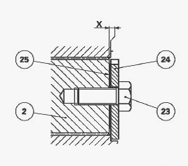
Determine a thickness of shims (25) greater than dimension X in order to
obtain a clearance. Install the washer (24) and the screw (23) and
tighten to a torque of 270-440 Nm. Using a dial gauge, check the
clearance by moving the planet carrier axially. Remove the screw (23)
and the washer (24). Depending on the dial gauge reading, remove the
surplus shim thickness (25) in order to obtain a preload of: P1 = 0.025
to 0.125 mm Clean the tapping at the end of the shaft (2). Reinstall the
washer (24). Clean the screw (23) and smear it with Loctite 241. Tighten
to a torque of 270-440 Nm.
Replacing the wheel stud
Drive out the defective stud using a bronze drift and a hammer. Use a
brush and some solvent to clean the serration marks left by the stud on
the shaft flange. Dry off with compressed air. Apply a few drops of
Loctite 270 to the new stud serration. Install the new stud over the
serration marks left by the previous stud. After checking that the
splines are properly engaged, bring the stud head up against the inner
flange of the axle shaft with a bronze drift.
________________________________________________________________________________
________________________________________________________________________________
________________________________________________________________________________________
 SPECS
SPECS LOADERS
 MAINTENANCE
 PROBLEMS
________________________________________________________________________________________
________________________________________________________________________________________
| MF TRACTORS SPECIFICATIONS |
 130
130 133
133 145
145 155
155 158
158________________________________________________________________________________________
 165
165 175
175 185
185 188
188 230
230________________________________________________________________________________________
 254
254 254S
254S 284S
284S 294
294 353
353________________________________________________________________________________________
 290
290 362
362 375
375 390
390 398
398________________________________________________________________________________________
 399
399 590
590 690
690 1010
1010 1030
1030________________________________________________________________________________________
 1020
1020 1150
1150 2620
2620 2640
2640 2645
2645________________________________________________________________________________________
 1540
1540 1736
1736 2660
2660 3065
3065 3095
3095________________________________________________________________________________________
 3650
3650 3680
3680 4255
4255 4355
4355 4370
4370________________________________________________________________________________________
 3630
3630 3635
3635 4245
4245 4445
4445 4609
4609________________________________________________________________________________________
 4710
4710 5435
5435 5475
5475 5610
5610 5711
5711________________________________________________________________________________________
 6150
6150 6170
6170 6180
6180 6270
6270 6290
6290________________________________________________________________________________________
 6445
6445 6499
6499 6614
6614 6713
6713 7465
7465________________________________________________________________________________________
 7495
7495 7614
7614 7622
7622 7715
7715 7726
7726________________________________________________________________________________________
 8210
8210 8270
8270 8650
8650 8727
8727 GC1705
________________________________________________________________________________________
| MF FRONT END LOADERS |
 1464 Loader
 1466 Loader
 1040 Loader
 1070 Loader
 905 Loader
________________________________________________________________________________________
 906 Loader
 915 Loader
 916 Loader
 921 Loader
 926 Loader
________________________________________________________________________________________
 931 Loader
 933 Loader
 936 Loader
 938 Loader
 939 Loader
________________________________________________________________________________________
 940 Loader
 941 Loader
 945 Loader
 946 Loader
 948 Loader
________________________________________________________________________________________
 949 Loader
 950 Loader
 951 Loader
 955 Loader
 956 Loader
________________________________________________________________________________________
 958 Loader
 960 Loader
 961 Loader
 965 Loader
 966 Loader
________________________________________________________________________________________
 968 Loader
 975 Loader
 976 Loader
 978 Loader
 985 Loader
________________________________________________________________________________________
 FL.3114 X
 FL.3419 X
 FL.3522
 FL.3615
 FL.3619
________________________________________________________________________________________
 FL.3817
 FL.3819
 FL.3823
 FL.4018
 FL.4121
 916X Loader
 921X Loader
 926X Loader
 931X Loader
 936X Loader
________________________________________________________________________________________
 941X Loader
 946X Loader
 951X Loader
 956X Loader
 988 Loader
________________________________________________________________________________________
 FL.4125
 FL.4227
 FL.4124
 FL.4220
 FL.4323
________________________________________________________________________________________
 FL.4327
 FL.4621
 FL.4624
 FL.4628
 FL.5033
________________________________________________________________________________________
 DL95 Loader
 DL100 Loader
 DL120 Loader
 DL125 Loader
 DL130 Loader
________________________________________________________________________________________
 DL135 Loader
 DL250 Loader
 DL260 Loader
 L90 Loader
 L100 Loader
________________________________________________________________________________________
 L105E Loader
 L210 Loader
 1014 Loader
 1016 Loader
 1462 Loader
________________________________________________________________________________________
 1525 Loader
 1530 Loader
 232 Loader
 838 Loader
 848 Loader
________________________________________________________________________________________
 246 Loader
 1036 Loader
 1038 Loader
 1080 Loader
 856 Loader
________________________________________________________________________________________
| MF TRACTORS MAINTENANCE |
 1010
1010 1020
1020 1030
1030 1035
1035 1040
1040________________________________________________________________________________________
 1045
1045 1080
1080 1085
1085 1120
1120 1125
1125________________________________________________________________________________________
 1140
1140 1160
1160 1165
1165 1180
1180 1190
1190________________________________________________________________________________________
 1205
1205 1210
1210 1215
1215 1220
1220 1225
1225________________________________________________________________________________________
 1230
1230 1233
1233 1235
1235 1240
1240 1260
1260________________________________________________________________________________________
| MF TRACTORS TROUBLESHOOTING | ||||
| 1652 | 1749 | 2620 | 2725 | 2805 |
| 3050 | 3120 | 3640 | 3709 | 4245 |
| 4455 | 5320 | 5455 | 5613 | 6150 |
| 6280 | 6480 | 6615 | 7618 | 7720 |