
________________________________________________________________________________
Massey Ferguson 6465, 6475, 6480 - Carraro suspended front axle control unit
Technical characteristics
Nominal pressure - 250 bar
Hydraulic oil type - DIN 51524
Ambient temperature - Min -30C / Max +90C
Hydraulic fluid temperature - Min -30C / Max +70C
Type of hydraulic unions to ports P, T, A, B - M18x1.5
Type of hydraulic unions to LS port - M14x1.5
Filtration: maximum pollution level allowed in service fluid - NAS 1638
Solenoid valve - 25 Nm
Accumulator tightening torque - 200 Nm
Nominal voltage - 12 VDC
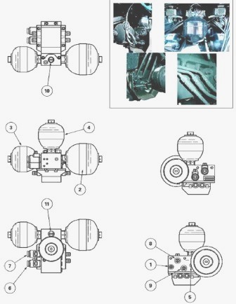
Parts list - (1) LS pilot flow (2) KSP1 accumulator (3)
KSP2 accumulator (4) RSP1 accumulator (5) Bleed screw (6) Solenoid valve
WV1 (7) Solenoid valve WV2 (8) Return (9) Supply from pump (10) Top ram
supply (11) Bottom ram supply
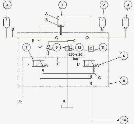
MF 6465, 6475, 6480 - Hydraulic description of
the control unit with Open Centre hydraulics
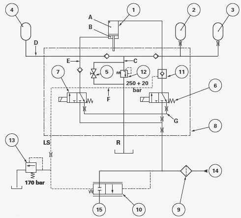
Parts list - (1) Front axle suspension ram (2) KSP1
accumulator (3) KSP2 accumulator (4) RSP1 accumulator (5) Bleed screw
(6) Solenoid valve WV1 (7) Solenoid valve WV2 (8) Control unit (9)
Filter (10) Proportional valve (11) Controlled non-return valve (12) 250
+ 20 bar pressure relief valve (13) 170 bar pressure relief valve (14)
High pressure inlet (15) To auxiliary spool valves, A - Upper ram
chamber, B - Lower ram chamber, C - Hydraulic channel, D - Hydraulic
channel, E - Hydraulic channel, F - LS pilot line, G - Hydraulic
channel, LS - Load Sensing pilot flow, R - Return to housing
Neutral position
In low position, chamber A of the ram (1) is empty. The suspension is in
contact with two mechanical central beam stops. In high position, the
ram is balanced by accumulators (2), (3) and (4). If the pressure in the
ram is too high (shocks received by the front axle), the pressure relief
valve (12) opens and the excess pressure is directed to the return. If
the ram position has changed, the position sensor value has also
changed. If after 3 seconds the sensor value does not match to the
calibration value, the calculator supplies the solenoid relevant
valve(s) (WV1 (6), WV2 (7)) to make the two values correspond.
Lifting position
When lifting, the two solenoid valves WV1 (6) and WV2 (7) are activated.
The WV1 solenoid valve (6) allows oil to reach the accumulators (2) and
(3) and chamber A of the ram (1). When the pressure in chamber B reaches
250 bar, the oil returns to the tank via channel C. Channel D also
supplies accumulator (4). Solenoid valve WV2 (7) allows priority for the
suspended front axle in pilot flow line F. The proportional valve (10)
stops the supply to the auxiliary spool valve and linkage. When the
pressure in the circuit reaches 180 bar, the circuit resumes its course
via the proportional valve (10) and supplies the linkage and auxiliary
valves.
Lowering position
When lowering, only solenoid valve WV2 (7) is supplied. The oil supplies
chamber B of the ram (1) via channel E. The pressure created in the
pilot flow line F allows priority for the suspended front axle. The
proportional valve (10) stops the supply to the auxiliary spool valve
and linkage. When the pressure in the circuit reaches 180 bar, the
circuit resumes its course via the proportional valve (10) and supplies
the linkage and auxiliary valves (15). The pressure in pilot flow line F
also allows the non-return valve (11) to open so that the oil in chamber
A returns to the tank via channel G.
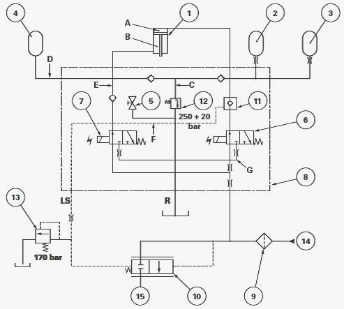
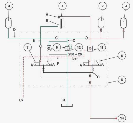
Massey Ferguson 6465, 6475, 6480 - Hydraulic description of the control
unit with Closed Centre hydraulics
Parts list - (1) Front axle suspension ram (2) KSP1 accumulator (3) KSP2
accumulator (4) RSP1 accumulator (5) Bleed screw (6) Solenoid valve WV1
(7) Solenoid valve WV2 (8) Control unit (11) Controlled non-return valve
(12) 250 + 20 bar pressure relief valve (14) High pressure inlet
Neutral position
In low position, chamber A of the ram (1) is empty. The suspension is in
contact with two mechanical central beam stops. In high position, the
ram is balanced by accumulators (2), (3) and (4). If the pressure in the
ram is too high (shocks received by the front axle), the pressure relief
valve (12) opens and the excess pressure is directed to the return. If
the ram position has changed, the position sensor value has also
changed. If after 3 seconds the sensor value does not match to the
calibration value, the calculator supplies the solenoid relevant
valve(s) (WV1 (6), WV2 (7)) to make the two values correspond.
Lifting position
When lifting, the two solenoid valves WV1 (6) and WV2 (7) are activated.
The WV1 solenoid valve (6) allows oil to reach the accumulators (2) and
(3) and chamber A of the ram (1). When the pressure in chamber B reaches
250 bar, the oil returns to the tank via channel C. Channel D also
supplies accumulator (4). Solenoid valve WV2 (7) allows priority for the
suspended front axle in pilot flow line F.
Lowering position
When lowering, only solenoid valve WV2 (7) is supplied. The oil supplies
chamber B of the ram (1) via channel E. The pressure created in the
pilot flow line F allows priority for the suspended front axle. The
pressure in pilot flow line F also allows the non-return valve (11) to
open so that the oil in chamber A returns to the tank via channel G.
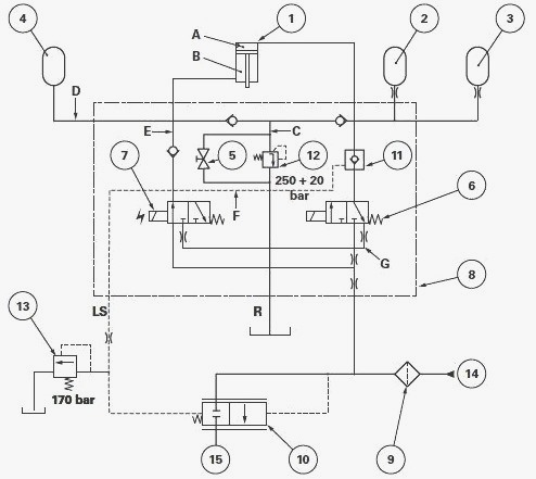
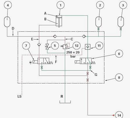
MF 6465, 6475, 6480 - Hydraulic description of the control unit with
Twin Flow Load Sensing hydraulics
The operation of the different positions (neutral, lifting and lowering)
of the hydraulic unit with Twin Flow hydraulics is similar to that
described. The only difference is that the hoses (pressure and LS) are
connected at different places.
Identification of ports
On the control unit
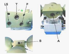
A - Supply (hydraulic chamber with a large section), B - Supply
(hydraulic chamber with a small section), LS - Load Sensing pilot flow,
P - High pressure, T - Return
On the tractor
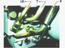
LS - Load Sensing pilot flow, P - High pressure, T - Return
Massey Ferguson 6465, 6475, 6480 - Disassembling and reassembling the
control unit
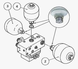
Some of the following pictures may not show your exact hydraulic control
unit, but the procedure is the same. Remove any components that could
hinder control unit removal. If necessary, remove the tractor complete
control unit. Disassembly - Mark the position of accumulators (2) (3)
(4) on the control unit. Remove them. The accumulators may be of
different capacity depending on their position and on the front axle
model. Loosen the A screw of each solenoid valve. Split the B solenoids
from C spools. Unscrew the C spools from the control unit. Gather the
components.
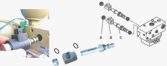
Reassembly - Check the components. Replace any defective parts. Screw
the C spools on the control unit. Tighten to a torque of 25 Nm. Assemble
the B solenoids on C spools. Tighten the A nuts moderately. If
necessary, fit new seals on each accumulator. Install the accumulators
using the marks made during removal. Tighten to a torque of 200 Nm. If
removed, Install the control unit on the tractor. Install any removed
components around the control unit. Screw the control unit AV bleed
screw. If the control unit and/or one or more solenoid valves needed to
be replaced: check P and LS pressure at the control unit ports;
calibrate the front axle.
________________________________________________________________________________
________________________________________________________________________________
________________________________________________________________________________________
 SPECS
SPECS LOADERS
 MAINTENANCE
 PROBLEMS
________________________________________________________________________________________
________________________________________________________________________________________
| MF TRACTORS SPECIFICATIONS |
 130
130 133
133 145
145 155
155 158
158________________________________________________________________________________________
 165
165 175
175 185
185 188
188 230
230________________________________________________________________________________________
 254
254 254S
254S 284S
284S 294
294 353
353________________________________________________________________________________________
 290
290 362
362 375
375 390
390 398
398________________________________________________________________________________________
 399
399 590
590 690
690 1010
1010 1030
1030________________________________________________________________________________________
 1020
1020 1150
1150 2620
2620 2640
2640 2645
2645________________________________________________________________________________________
 1540
1540 1736
1736 2660
2660 3065
3065 3095
3095________________________________________________________________________________________
 3650
3650 3680
3680 4255
4255 4355
4355 4370
4370________________________________________________________________________________________
 3630
3630 3635
3635 4245
4245 4445
4445 4609
4609________________________________________________________________________________________
 4710
4710 5435
5435 5475
5475 5610
5610 5711
5711________________________________________________________________________________________
 6150
6150 6170
6170 6180
6180 6270
6270 6290
6290________________________________________________________________________________________
 6445
6445 6499
6499 6614
6614 6713
6713 7465
7465________________________________________________________________________________________
 7495
7495 7614
7614 7622
7622 7715
7715 7726
7726________________________________________________________________________________________
 8210
8210 8270
8270 8650
8650 8727
8727 GC1705
________________________________________________________________________________________
| MF FRONT END LOADERS |
 1464 Loader
 1466 Loader
 1040 Loader
 1070 Loader
 905 Loader
________________________________________________________________________________________
 906 Loader
 915 Loader
 916 Loader
 921 Loader
 926 Loader
________________________________________________________________________________________
 931 Loader
 933 Loader
 936 Loader
 938 Loader
 939 Loader
________________________________________________________________________________________
 940 Loader
 941 Loader
 945 Loader
 946 Loader
 948 Loader
________________________________________________________________________________________
 949 Loader
 950 Loader
 951 Loader
 955 Loader
 956 Loader
________________________________________________________________________________________
 958 Loader
 960 Loader
 961 Loader
 965 Loader
 966 Loader
________________________________________________________________________________________
 968 Loader
 975 Loader
 976 Loader
 978 Loader
 985 Loader
________________________________________________________________________________________
 FL.3114 X
 FL.3419 X
 FL.3522
 FL.3615
 FL.3619
________________________________________________________________________________________
 FL.3817
 FL.3819
 FL.3823
 FL.4018
 FL.4121
 916X Loader
 921X Loader
 926X Loader
 931X Loader
 936X Loader
________________________________________________________________________________________
 941X Loader
 946X Loader
 951X Loader
 956X Loader
 988 Loader
________________________________________________________________________________________
 FL.4125
 FL.4227
 FL.4124
 FL.4220
 FL.4323
________________________________________________________________________________________
 FL.4327
 FL.4621
 FL.4624
 FL.4628
 FL.5033
________________________________________________________________________________________
 DL95 Loader
 DL100 Loader
 DL120 Loader
 DL125 Loader
 DL130 Loader
________________________________________________________________________________________
 DL135 Loader
 DL250 Loader
 DL260 Loader
 L90 Loader
 L100 Loader
________________________________________________________________________________________
 L105E Loader
 L210 Loader
 1014 Loader
 1016 Loader
 1462 Loader
________________________________________________________________________________________
 1525 Loader
 1530 Loader
 232 Loader
 838 Loader
 848 Loader
________________________________________________________________________________________
 246 Loader
 1036 Loader
 1038 Loader
 1080 Loader
 856 Loader
________________________________________________________________________________________
| MF TRACTORS MAINTENANCE |
 1010
1010 1020
1020 1030
1030 1035
1035 1040
1040________________________________________________________________________________________
 1045
1045 1080
1080 1085
1085 1120
1120 1125
1125________________________________________________________________________________________
 1140
1140 1160
1160 1165
1165 1180
1180 1190
1190________________________________________________________________________________________
 1205
1205 1210
1210 1215
1215 1220
1220 1225
1225________________________________________________________________________________________
 1230
1230 1233
1233 1235
1235 1240
1240 1260
1260________________________________________________________________________________________
| MF TRACTORS TROUBLESHOOTING | ||||
| 1652 | 1749 | 2620 | 2725 | 2805 |
| 3050 | 3120 | 3640 | 3709 | 4245 |
| 4455 | 5320 | 5455 | 5613 | 6150 |
| 6280 | 6480 | 6615 | 7618 | 7720 |