
________________________________________________________________________________
Massey Ferguson 6465, 6475, 6480 - Carraro Front Axle Suspension
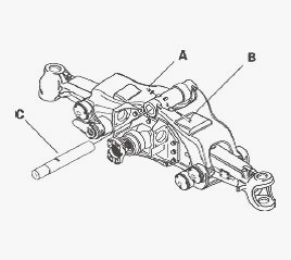
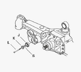
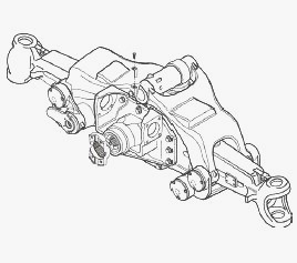
Massey Ferguson 6465, 6475, 6480 - Disassembling the arm assembly
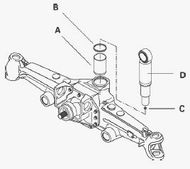
Lock the arms using a suitable lifting mechanism to prevent any untimely
movement. Loosen the nut A and extract the taper pin B. Remove the pivot
pin C using a rubber mallet or another soft object if required.
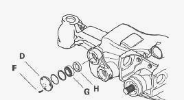
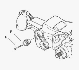
Remove the pin covers of the upper arms D at the front and rear of the
arms, loosening the relevant attachment screws (F). Recover the seals
and shims if present. Note the position of all disassembled elements.
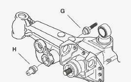
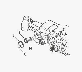
Remove the bearing G and the clamp ring H of each pin.
Remove the attachment screws I of the arm pins and extract the pins J
using a suitable extracting tool inserted into the threaded hole
provided in the pin for this purpose (screw M16x100).
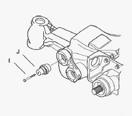
To make the extraction easier, the arm pin housing can be heated to a
maximum temperature of 100C. This operation will destroy the seals.
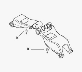
Remove the upper arms with a suitable lifting tool. Recover the seals
and shims if present. Replace the shock absorber pads K if necessary by
removing the relevant screws.
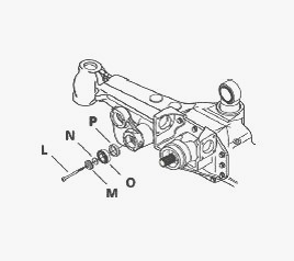
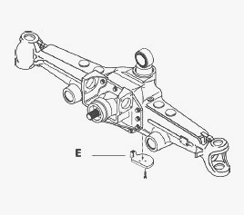
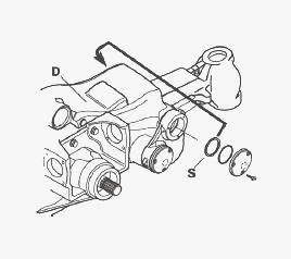
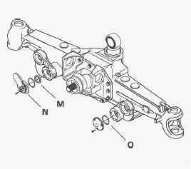
Remove the lower arm pin covers and the sensor E plate by loosening the
relevant attachment screws F. Recover the rubber guide of the sensor.
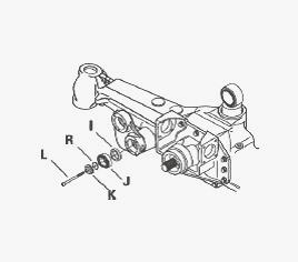
Remove the attachment screws L of the arm pin bearings and recover the
relevant thrust washer M and shims N, if used. The thrust washer fitted
on the sensor pin has a special shape and must not be confused with
another washer. To reach the attachment screw on the side of the sensor,
the mounting bush must be removed from the dust seal. This operation
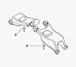
will destroy the seals. Remove the bearings O and seals P.
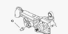
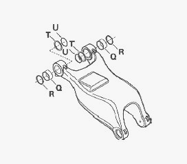
Remove the pins Q from the arms using a suitable extractor inserted into
the threaded hole provided for this purpose (screw M16x100).
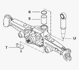
Take on the attachment screws to remove the lower cover T. Extract the
axle beam cylinder. Extract the O’ring U from the cylinder and the seal
R from its housing in the axle beam. Do not replace the ring S unless
necessary, using a suitable extracting tool.
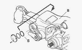
Massey Ferguson 6465, 6475, 6480 - Reassembling the arm assembly
Install ring A, previously smeared with Loctite 510, in its position in
the control ram housing. Install the seal B on the axle beam and a new
O’ring C lightly smeared with grease in the housing at the bottom of the
control ram D. Install the ram in the axle beam.
Install the lower cover E on the lower part of the axle beam and tighten
the relevant attachment screws to the required torque using a torque
wrench. Before installing the cover, make sure that the O’ring is
correctly positioned at the bottom of the ram.
Install the lower arms on the axle beam and align the pins by inserting
special tool into the housing at the side opposite the pin assembly.
Install the arm pins H into the holes provided in the arms and axle
beam, and push them home in their holes using special tool.
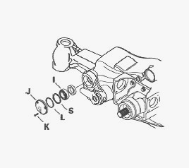
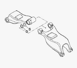
Install one seal I onto each pin fitted in the lower arm housing using
special tool and a mallet. Install a roller bearing. Install a spacer R
(on the drive pinion side) of the correct dimensions (thickness: R=1mm)
and install the thrust washer K fitted with the attachment screw L.
The spacer outside diameter must be smaller than the bearing internal
diameter. The thrust washer fitted on the sensor pin has a special shape
and must not be confused with another washer. Shim the taper roller
bearings by moving the axle beam arms and tighten the attachment screws
to the required torque using a torque wrench. Check the assembly
position of the bearings on the arms. On the lower pins of the arms: the
bearing must be fitted with the cup facing inwards (in the arm housing)
and the cone facing outwards (on the pin).
On the upper arms: the
bearing must be fitted with the cone on the inside (on the pin) and the
cup on the outside (on the arm housing). Place a dial gauge with a
magnetic stand on the axle beam and move the dial gauge feeler pin until
it comes into contact with the face of the lower arm, then reset the
dial gauge to zero. Install a lever between the arm and the axle beam,
push the arm home at each side and measure the clearance using a dial
gauge. Repeat this operation several times to obtain an average value X.
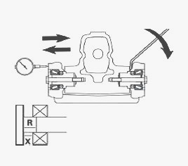
To determine the thickness S to obtain the required bearing preload,
subtract the measured value X and the recommended value from the known
reference value R: S = (R - X) - V. V = 0.05 to 0.15 mm. Select from the
available shims the number required to obtain the thickness S defined
previously. Remove the attachment screws L on the gear side and the
reference shim R. Insert shims S between the stop K and the taper roller
bearing J. All shims must be inserted, and only on the drive pinion
side. Reassemble the attachment screws: apply Loctite 542 to the
threads, then tighten the screws to the required torque using a torque
wrench. Repeat the described procedure on the lower arm.
Place the upper arms on a workbench with a suitable lifting device. If
shock absorber pad P must be replaced, tighten the attachment screws to
the required torque using a torque wrench.
Install the two rings Q in the pivot pin housings on the fork of the
arm. It is advisable to cool the rings to a temperature below -100C to
make their assembly easier. It is recommended to wear protective gloves.
Assemble the seals. Install the spacers T on the internal side of the
fork and place the corresponding O’ring U into the spacer housings.
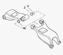
Insert the spacer Z into the housing of the other pivot pin and the
corresponding O’ring V. On the other side Install the dummy thrust
washer W in the spacer housing. Check that the dummy thrust washer
remains in position when assembling the arms, then replace it with shims
after measuring the spacer clearance.
Using a suitable lifting mechanism, position the upper arms on the axle
beam and link them to the lower arms. Fully insert the pins F in the
housings provided in each arm. It is advisable to cool the arms to a
temperature below -100C to make their assembly easier. Reassemble the
attachment screws E. Apply Loctite 542 to the threads, then tighten the
screws to the required torque using a torque wrench.
Install a seal H to each arm pin using the special tool. Install a
roller bearing. Install the cover J with its attachment screws K. Shim
the taper roller bearings by moving the axle beam arms and tighten the
attachment screws to the required torque using a torque wrench.
Place a dial gauge with a magnetic stand on the upper arm and move the
dial gauge feeler pin until it comes into contact with the lower arm,
then reset the dial gauge to zero. Install a lever between the upper and
lower arm, push the arm home on each side and measure the clearance X
between the bearings and their housings, using the dial gauge. Repeat
this operation several times to obtain an average value.
To determine
the thickness S required to obtain the required bearing preload, add
together the measured value X and the recommended value V: S = X + V. V
= 0.05 to 0.15 mm. Select from the available shims the number required
to obtain the thickness S defined previously. Repeat the described
procedure on the other upper arm. Remove the arm pin covers on the gear
side, Install shims S and a new O’ring L and assemble, filling their
housing with grease and tightening the attachment screws K to the
required torque.
Remove the covers from the side opposite the pinion, fill their housings
with grease, then reinstall with a new O’ring L. Shims must be
introduced on the drive pinion side. Tighten the attachment screws K
with a torque wrench to the requested torque. Align the arms, ram head
holes and washers (if present).
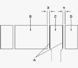
Simultaneously measure the dimensions X between the arm B and ram head
C, and Y between the arm D and ram head C. Use two long shims, holding
washers A in place. The minimum length of shims must be equal to the
outer diameter of the ram head. The clearance X must be at least 0.10mm.
If not, move the shims S in the upper left-hand arm B across to the
opposite housing of the same arm.
The clearance Y must be at least 0.10mm. If not, move the shims S in the
upper right-hand arm D across to the opposite housing of the same arm.
Install the locating pin and adjust the components. Using a shim
thickness Z, measure the distance between the spacer T and the dummy
thrust washer W. Remove the dummy thrust washer, then extract the
locating pin to remove the spacer housings located on the arms.
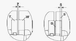
To determine the thickness S required to obtain the necessary clearance
at the arms, calculate: S = Z - V. V = 0.4 to 0.7 mm. Select from the
available shims the number required to obtain the thickness S defined
previously: Install the selected shims S and the spacer D in place of
the dummy thrust washer.
Align the ports of the arms and control ram; insert the pivot pin, then
fit it to the bottom of its housing. Keep the special tool at the
opening of the pin housing. Lock the pivot pin with the taper pin Q and
screw the nut R to the required torque using a torque wrench. Extract
the attachment screws from all lower arm pins and reinstall the
assemblies, applying Loctite 542 to the threads then tightening the
screws to the required torque using a torque wrench. Install the seal M
to the thrust washer of the sensor pin and Install new O’rings in their
housing on the covers O of the arms and on the plate N of the sensor.
Install the arm pin covers and the sensor plate, fill their housing with
grease and tighten the relevant attachment screws to the required
torque.
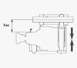
Measure the distance Xac in Axle closed position between the pivot pin
centre and the differential housing, choosing an exact reference point
P.
Fully raise the axle beam arm and measure the distance Xaa in Axle open
position between the pivot pin centre and the selected reference point
P.
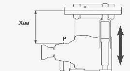
Check that travel C of the control ram remains within the allowable
limits, by subtracting the measured dimensions as follows: C = Xaa -
Xac. C= 88 to 89 mm. If the travel C of the suspension cylinder is not
within allowable limits, measure the clearance X between the upper arms
at the point of insertion of shims in Axle open position.
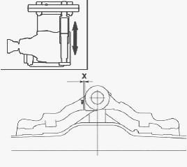
To determine the thickness S required for the correct end-of-travel
position for the arms, add the measured value X to the recommended value
V: S = X + V. V = 0.3 mm.
Select from the available shims the number required to obtain the
thickness S defined previously. Lower the upper arms of the axle beam
(Axle closed position) and insert the shims selected with their
attachment screws. Lift the axle beam to maximum position again (Axle
open) to position the arms correctly, then return to the initial
position (Axle closed). Ensure that suspension cylinder travel C remains
in the allowable limits.
________________________________________________________________________________
________________________________________________________________________________
________________________________________________________________________________________
 SPECS
SPECS LOADERS
 MAINTENANCE
 PROBLEMS
________________________________________________________________________________________
________________________________________________________________________________________
| MF TRACTORS SPECIFICATIONS |
 130
130 133
133 145
145 155
155 158
158________________________________________________________________________________________
 165
165 175
175 185
185 188
188 230
230________________________________________________________________________________________
 254
254 254S
254S 284S
284S 294
294 353
353________________________________________________________________________________________
 290
290 362
362 375
375 390
390 398
398________________________________________________________________________________________
 399
399 590
590 690
690 1010
1010 1030
1030________________________________________________________________________________________
 1020
1020 1150
1150 2620
2620 2640
2640 2645
2645________________________________________________________________________________________
 1540
1540 1736
1736 2660
2660 3065
3065 3095
3095________________________________________________________________________________________
 3650
3650 3680
3680 4255
4255 4355
4355 4370
4370________________________________________________________________________________________
 3630
3630 3635
3635 4245
4245 4445
4445 4609
4609________________________________________________________________________________________
 4710
4710 5435
5435 5475
5475 5610
5610 5711
5711________________________________________________________________________________________
 6150
6150 6170
6170 6180
6180 6270
6270 6290
6290________________________________________________________________________________________
 6445
6445 6499
6499 6614
6614 6713
6713 7465
7465________________________________________________________________________________________
 7495
7495 7614
7614 7622
7622 7715
7715 7726
7726________________________________________________________________________________________
 8210
8210 8270
8270 8650
8650 8727
8727 GC1705
________________________________________________________________________________________
| MF FRONT END LOADERS |
 1464 Loader
 1466 Loader
 1040 Loader
 1070 Loader
 905 Loader
________________________________________________________________________________________
 906 Loader
 915 Loader
 916 Loader
 921 Loader
 926 Loader
________________________________________________________________________________________
 931 Loader
 933 Loader
 936 Loader
 938 Loader
 939 Loader
________________________________________________________________________________________
 940 Loader
 941 Loader
 945 Loader
 946 Loader
 948 Loader
________________________________________________________________________________________
 949 Loader
 950 Loader
 951 Loader
 955 Loader
 956 Loader
________________________________________________________________________________________
 958 Loader
 960 Loader
 961 Loader
 965 Loader
 966 Loader
________________________________________________________________________________________
 968 Loader
 975 Loader
 976 Loader
 978 Loader
 985 Loader
________________________________________________________________________________________
 FL.3114 X
 FL.3419 X
 FL.3522
 FL.3615
 FL.3619
________________________________________________________________________________________
 FL.3817
 FL.3819
 FL.3823
 FL.4018
 FL.4121
 916X Loader
 921X Loader
 926X Loader
 931X Loader
 936X Loader
________________________________________________________________________________________
 941X Loader
 946X Loader
 951X Loader
 956X Loader
 988 Loader
________________________________________________________________________________________
 FL.4125
 FL.4227
 FL.4124
 FL.4220
 FL.4323
________________________________________________________________________________________
 FL.4327
 FL.4621
 FL.4624
 FL.4628
 FL.5033
________________________________________________________________________________________
 DL95 Loader
 DL100 Loader
 DL120 Loader
 DL125 Loader
 DL130 Loader
________________________________________________________________________________________
 DL135 Loader
 DL250 Loader
 DL260 Loader
 L90 Loader
 L100 Loader
________________________________________________________________________________________
 L105E Loader
 L210 Loader
 1014 Loader
 1016 Loader
 1462 Loader
________________________________________________________________________________________
 1525 Loader
 1530 Loader
 232 Loader
 838 Loader
 848 Loader
________________________________________________________________________________________
 246 Loader
 1036 Loader
 1038 Loader
 1080 Loader
 856 Loader
________________________________________________________________________________________
| MF TRACTORS MAINTENANCE |
 1010
1010 1020
1020 1030
1030 1035
1035 1040
1040________________________________________________________________________________________
 1045
1045 1080
1080 1085
1085 1120
1120 1125
1125________________________________________________________________________________________
 1140
1140 1160
1160 1165
1165 1180
1180 1190
1190________________________________________________________________________________________
 1205
1205 1210
1210 1215
1215 1220
1220 1225
1225________________________________________________________________________________________
 1230
1230 1233
1233 1235
1235 1240
1240 1260
1260________________________________________________________________________________________
| MF TRACTORS TROUBLESHOOTING | ||||
| 1652 | 1749 | 2620 | 2725 | 2805 |
| 3050 | 3120 | 3640 | 3709 | 4245 |
| 4455 | 5320 | 5455 | 5613 | 6150 |
| 6280 | 6480 | 6615 | 7618 | 7720 |