
________________________________________________________________________________
Massey Ferguson 6465, 6475, 6480 - Ground Speed PTO
Ground speed power take-off may be available (depending on option) on MF
6465, 6475, 6480 tractors. In contrast to the independent PTO mechanism
where the speed of the rear PTO output shaft depends on the speed of the
engine, Ground Speed PTO is driven by the pinion and a set of gears also
used by the 4WD clutch unit. The speed of the rear PTO output shaft is
therefore proportional to the tractor's travel speed.
Massey Ferguson 6465, 6475, 6480 Ground Speed
PTO - Construction and Operation
Construction
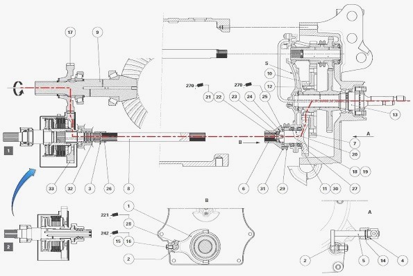
The pinion of the rear crownwheel and pinion supports the driving gear
(17), which is constantly meshed with the bell gear (33) of the 4WD
clutch unit. On the ground speed PTO, the gear (27) is constantly meshed
with the driven gear (10), which is attached to the 540 rpm driven gear
(7) by the screw (12). This gear is itself splined to the output shaft
(13) of the rear PTO.
Operation
The forward movement of the coupler (31) allows the movement transmitted
by the gears (17) (33) to travel towards the output shaft (13) of the
rear PTO via the shaft (8) and the gears (27) (10). The coupling is
activated by an external rod located at the bottom right of the rear PTO
housing. This rod is connected to a cable, which is connected to a
control lever accessible from the cab. A switch connected to this
control lever electronically controls the engagement of the ground speed
PTO. When the Ground speed power take-off is engaged, the independent
540 - 1000 rpm PTO is deactivated.

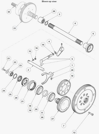
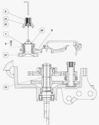
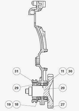
Parts list: (1) Fork (2) Selector rail (3) Circlip (4)
Snap ring (5) Control pin/finger (6) Splined sleeve (7) 540 rpm driven
gear (8) Shaft (9) Pinion (10) Driven gear (11) Bearing cone (12) Screw
(13) Output shaft (14) "O" ring (15) Pushrod screw (16) Nut (17) Driving
gear (4WD) (18) Bearing cone (19) Bearing cup (20) Shim(s) (21)
Countersunk screw (22) Chamfered washer (23) Ball bearing (24) Circlip
(25) Nut (26) Sleeve (27) Driving gear/shaft assembly (28) Set screw
(29) Hub (30) Bearing cup (31) Coupler (32) 4WD shaft (33) Bell gear
(4WD), A - Details, B - Details, S - Removable support
Massey Ferguson 6465, 6475, 6480 Ground Speed
PTO - Removing and install the selection mechanism and adjusting the
pushrod screw
Removing the selection mechanism
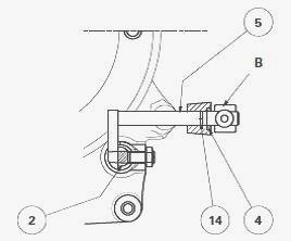
Disconnect the PTO housing from the centre housing. Remove rod B. Remove
the snap ring (4). Separate the control pin/finger (5) from the selector
rail (2). Turn it approx. 90° and pull it out of the PTO housing in
order to remove the "O" ring (14). Remove the control pin/finger (5) by
pushing it along its entire length towards the inside of the PTO
housing. Unscrew the nut (16) and the pushrod screw (15) on the selector
rail (2). Unscrew the set screw (28). Remove the selector rail (2) and
the fork (1).
Install the selection mechanism
Clean and check all components. Replace those that are defective.
Install the fork and the selector rail. Lightly smear the thread of the
set screw (28) with Loctite 221 or equivalent. Tighten this screw to a
torque of 25-35 Nm. From the inside of the PTO housing, Install the
control pin/finger (5) in its position and press it fully back towards
the outside of the housing. Lubricate a new "O" ring (14). From the
outside of the PTO housing, Install the new "O" ring (14) in the groove
of the protruding section of the control pin/finger. Push the control
pin/finger assembly back inside the PTO housing. Position it in the slot
on the selector rail (2). Reinstall: new snap ring (4); control rod B.
Lightly smear the thread of the screw on control rod B with Loctite 221
or equivalent. Tighten this screw to a torque of 25-35 Nm. Check the
movement of rod B.
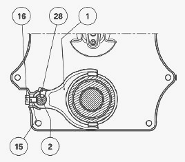
Adjusting the pushrod screw
Position the selector rail (2) so that its flat section is opposite the
tapped hole of the pushrod screw (15). Tighten the pushrod screw (15)
without forcing it in order to compress the ball, then loosen it by one
quarter turn. Clean the thread of the pushrod screw (15) and the nut
(16). Lightly smear the thread of the nut (16) with Loctite 242 or
equivalent. Tighten this nut to 15-20 Nm while holding the pushrod screw
in place. Check that the fork lock matches. Reconnect the PTO housing to
the centre housing. Start the tractor engine and check the ground speed
PTO operation.
Massey Ferguson 6465, 6475, 6480 Ground Speed
PTO - Disassembly and reassembly the gears
Ground speed power take-off comprises a driving gear train (17) (33) and
a driven gear train (27) (10) located respectively at the front and rear
of the centre housing.
If work is necessary on the driving
gear train (17) (33), proceed as follows:
1) To access the gear (17) - Disconnect the tractor between the gearbox
and the centre housing. Remove the gear (17).
2) To access the gear (33) (MF 6465, 6475) - Remove the 4WD clutch unit.
3) To access the gear (33) (MF 6465, 6480) - Disconnect the tractor
between the gearbox and the centre housing. Remove the 4WD clutch unit.
If work is necessary on the driven gear train (27) (10) (all types of
transmission except GTA1540 (50 kph)), remove the rear PTO housing. The
lower bearing and removable support S are also removed with this housing
during the operation.
Ground Speed PTO gears disassembly
Disconnect the PTO housing from the centre housing. Place the housing in
a horizontal position with the gears facing upwards as required. Loosen
the nut (16) and the pushrod screw (15) for the 540-1000 rpm selector
rail. Remove the ground speed PTO selection mechanism. Loosen the
countersunk screw (21). Recover the chamfered washer (22).
Remove the splined sleeve (6). Unlock the nut (25). Immobilise the
output shaft using a locally obtained M16 screw. Partially loosen the
nut (25) using a standard socket (55 mm flat). The nut (25) must be
unlocked before removing removable support S in order to take advantage
of the opportunity to lock the output shaft (13) with the M16 screw.
Remove removable support S using bearings at the front ends of the PTO
shafts (upper and lower). Finish unscrewing the nut (25) and remove it.
Also remove: hub (29) and the coupler (31); bearing cone (18) (to be
paired with the cup (19) if it is to be re-used); shims (20); bearing
cone (11) (to be paired with the cup (30) if it is to be re-used);
gear/shaft assembly (27).
Drive out the bearing cups (19) (30) from the removable support. If
necessary, visually note the position of the shaft (8) and remove it
along with the sleeve (26). Remove the circlip (3). The undercut end of
the shaft (8) is positioned towards the 4WD clutch unit. If necessary,
remove the driven gear (10), which is centred and fitted to the 540 rpm
gear (7) via a screw. The method of fitting one gear against another has
already been used in chapter 7 in the section on the GPA40 output shaft
and brake). Strip the sleeve (6) by carrying out the following steps:
Remove the circlip (24). Drive out the ball bearing (23).
Ground Speed PTO gears reassembly
Clean and check all components. Replace those that are defective.
Assemble the sleeve by carrying out the following steps: Install the
ball bearing (23) using a suitable fitting drift whose external diameter
should be slightly less than the external diameter of the ball bearing.
Install the circlip (24). If necessary, reinstall: driven gear (10);
circlip (3) in the sleeve (26); shaft (8). Install the bearing cups (19)
(30) against the removable support cord. Shim the bearings (11) (30) and
(18) (19) of the gear/shaft assembly (27). Install the removable
support. Tighten the V screws to a torque of 68-92 Nm. Clean the threads
of the new nut (25) and the gear pin (27). Lightly smear the nut thread
with Loctite 270 or equivalent. Immobilise the output shaft. Correctly
position the nut. Definitively tighten to 160-240 Nm.
Using a suitable punch, lock the nut in place by bending the collar into
the grooves of the shaft without breaking it. Reinstall the coupler (31)
and the splined sleeve (6). Correctly position the chamfered washer (22)
and install it to the ball bearing (23). Lightly smear the thread of the
countersunk screw (21) with Loctite 270 or equivalent. Tighten this
screw to a torque of 24-28 Nm. Reinstall and adjust the ground speed PTO
selection mechanism. Install the pushrod screw (15) and the nut (16) of
the 540-1000 rpm selector rail. Adjust the pushrod screw. Reconnect the
PTO housing to the centre housing. Start the tractor engine and check
the Ground speed power take-off operation.
Massey Ferguson 6465, 6475, 6480 Ground Speed
PTO - Shimming the gear/shaft assembly bearings

The gear/shaft assembly (27) is shimmed with removable support S. The
removable support must be removed from the rear PTO housing assembly and
clamped in a vice fitted with protective jaws.
Preparing for shimming
Assemble the gear/shaft assembly (27) with the bearing cones (11) (18)
lightly lubricated. Separate the bearing cones by a shim (20) thickness
in order to obtain a temporary clearance of approx. 0.10 to 0.15 mm.
Install the hub (29). Immobilise the gear/shaft assembly (27) using a
makeshift tool. Temporarily tighten the nut (25) to 30 - 50 Nm with no
Loctite on its thread.
Shimming
Place the feeler pin of a dial gauge on the end of the gear/shaft
assembly (27). Using the appropriate levers, apply diametrically opposed
pressure on the gear of the gear/shaft assembly (27) by pulling on this
assembly in order to fit the cone (18) in its bearing cup. With the help
of an operator, set the dial gauge needle to zero. Repeat, pulling on
the hub (29) in order to Install the cone (11) in its bearing cup.
According to the temporary clearance reading measured on the dial gauge,
determine another shim (20) thickness to obtain a preload P1 = 0.05 to
0.15 mm. As far as possible, shim to the maximum tolerance. Loosen and
remove the nut. Remove the hub (29) and the bearing cone (18). Install
the shims between the two bearing cones (11) (18). Reinstall the hub.
Lock the nut (25) again to a torque of 30-50 Nm, with no Loctite on its
thread, in order to manually check the rotation of the gear.
MF 6465, 6475, 6480 Ground Speed PTO -
Assembling and adjusting the control
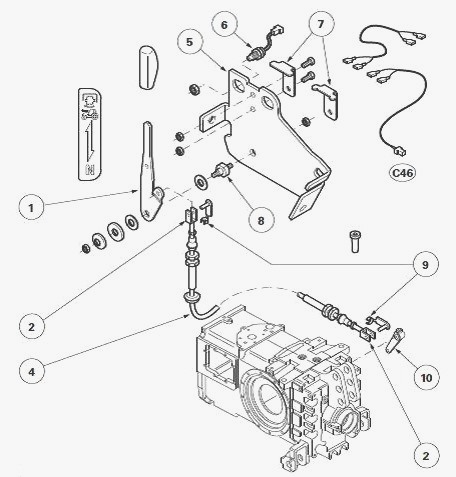
Parts list: (1) Lever (2) Clevises (4) Cable (5)
Support (6) Switch (7) Stops (8) Pin (9) Clips (10) Connecting rod
Install the control, lever side
Preparing the cable - If possible, tighten the clevis (2) to the maximum
against the cable (4). Tighten the nut (3).
Assembly - Link the clevis to the lever (1) using the clip (9). Tighten
the sheath end to the support (5) using nuts (11).
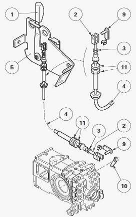
Install and adjusting the control, centre
housing side
Preparing the cable - If possible, tighten the clevis (2) to the maximum
against the cable (4). Tighten the nut (3).
Assembly - Slide the sheath end of the cable onto the support fitted to
the right of the housing assembly. Place the lever (1) and the rod (10)
in Ground speed power take-off position. Connect the clevis (2) to the
rod (10) using the clip (9).
Settings
Adjust the sheath end on the support using the nuts (11) and without
moving the rod (10). Tighten the nuts. Check that the control moves
freely in each position (neutral and engaged). The coupler has spur cut
teeth: it can only be controlled if the tractor is almost stationary.
________________________________________________________________________________
________________________________________________________________________________
________________________________________________________________________________________
 SPECS
SPECS LOADERS
 MAINTENANCE
 PROBLEMS
________________________________________________________________________________________
________________________________________________________________________________________
| MF TRACTORS SPECIFICATIONS |
 130
130 133
133 145
145 155
155 158
158________________________________________________________________________________________
 165
165 175
175 185
185 188
188 230
230________________________________________________________________________________________
 254
254 254S
254S 284S
284S 294
294 353
353________________________________________________________________________________________
 290
290 362
362 375
375 390
390 398
398________________________________________________________________________________________
 399
399 590
590 690
690 1010
1010 1030
1030________________________________________________________________________________________
 1020
1020 1150
1150 2620
2620 2640
2640 2645
2645________________________________________________________________________________________
 1540
1540 1736
1736 2660
2660 3065
3065 3095
3095________________________________________________________________________________________
 3650
3650 3680
3680 4255
4255 4355
4355 4370
4370________________________________________________________________________________________
 3630
3630 3635
3635 4245
4245 4445
4445 4609
4609________________________________________________________________________________________
 4710
4710 5435
5435 5475
5475 5610
5610 5711
5711________________________________________________________________________________________
 6150
6150 6170
6170 6180
6180 6270
6270 6290
6290________________________________________________________________________________________
 6445
6445 6499
6499 6614
6614 6713
6713 7465
7465________________________________________________________________________________________
 7495
7495 7614
7614 7622
7622 7715
7715 7726
7726________________________________________________________________________________________
 8210
8210 8270
8270 8650
8650 8727
8727 GC1705
________________________________________________________________________________________
| MF FRONT END LOADERS |
 1464 Loader
 1466 Loader
 1040 Loader
 1070 Loader
 905 Loader
________________________________________________________________________________________
 906 Loader
 915 Loader
 916 Loader
 921 Loader
 926 Loader
________________________________________________________________________________________
 931 Loader
 933 Loader
 936 Loader
 938 Loader
 939 Loader
________________________________________________________________________________________
 940 Loader
 941 Loader
 945 Loader
 946 Loader
 948 Loader
________________________________________________________________________________________
 949 Loader
 950 Loader
 951 Loader
 955 Loader
 956 Loader
________________________________________________________________________________________
 958 Loader
 960 Loader
 961 Loader
 965 Loader
 966 Loader
________________________________________________________________________________________
 968 Loader
 975 Loader
 976 Loader
 978 Loader
 985 Loader
________________________________________________________________________________________
 FL.3114 X
 FL.3419 X
 FL.3522
 FL.3615
 FL.3619
________________________________________________________________________________________
 FL.3817
 FL.3819
 FL.3823
 FL.4018
 FL.4121
 916X Loader
 921X Loader
 926X Loader
 931X Loader
 936X Loader
________________________________________________________________________________________
 941X Loader
 946X Loader
 951X Loader
 956X Loader
 988 Loader
________________________________________________________________________________________
 FL.4125
 FL.4227
 FL.4124
 FL.4220
 FL.4323
________________________________________________________________________________________
 FL.4327
 FL.4621
 FL.4624
 FL.4628
 FL.5033
________________________________________________________________________________________
 DL95 Loader
 DL100 Loader
 DL120 Loader
 DL125 Loader
 DL130 Loader
________________________________________________________________________________________
 DL135 Loader
 DL250 Loader
 DL260 Loader
 L90 Loader
 L100 Loader
________________________________________________________________________________________
 L105E Loader
 L210 Loader
 1014 Loader
 1016 Loader
 1462 Loader
________________________________________________________________________________________
 1525 Loader
 1530 Loader
 232 Loader
 838 Loader
 848 Loader
________________________________________________________________________________________
 246 Loader
 1036 Loader
 1038 Loader
 1080 Loader
 856 Loader
________________________________________________________________________________________
| MF TRACTORS MAINTENANCE |
 1010
1010 1020
1020 1030
1030 1035
1035 1040
1040________________________________________________________________________________________
 1045
1045 1080
1080 1085
1085 1120
1120 1125
1125________________________________________________________________________________________
 1140
1140 1160
1160 1165
1165 1180
1180 1190
1190________________________________________________________________________________________
 1205
1205 1210
1210 1215
1215 1220
1220 1225
1225________________________________________________________________________________________
 1230
1230 1233
1233 1235
1235 1240
1240 1260
1260________________________________________________________________________________________
| MF TRACTORS TROUBLESHOOTING | ||||
| 1652 | 1749 | 2620 | 2725 | 2805 |
| 3050 | 3120 | 3640 | 3709 | 4245 |
| 4455 | 5320 | 5455 | 5613 | 6150 |
| 6280 | 6480 | 6615 | 7618 | 7720 |