
________________________________________________________________________________
Massey Ferguson 6465, 6480, 6485 - Rear axle brake pistons
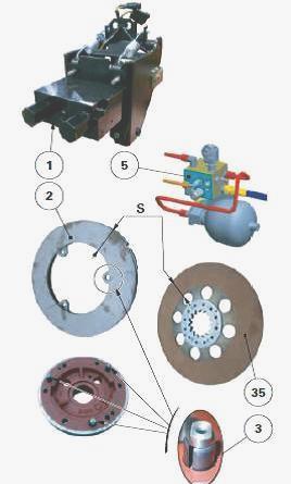
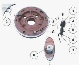
The brake pistons (2) are housed in two cavities formed by the centre
housing and the left and right-hand differential supports. They are:
concentric with the mating face of each trumpet housing; guided by three
stop pins (6) force fitted into the centre housing. Each brake piston
has two ring faces F and F1, which have different cross sections.
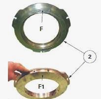
Face F is under hydraulic pressure: from the master cylinders (MF 6465,
6480 tractors); from a block/valves assembly (MF 6485, 6490 tractors).
Face F1 compresses the brake disc, which is splined to the input sun
gear of the trumpet housing, against the compartment or spacer,
depending on the trumpet housing type. The compartment or spacer also
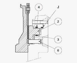
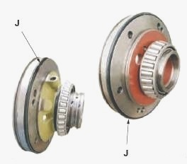
acts as a brake plate. The pistons are sealed by "O"rings (3) (4)
mounted respectively into the grooves of the centre housing and the
differential supports. A seal J placed in the angle of each support
prevents the pressure in the piston chamber from escaping into the
centre housing.
MF 6465, 6480 Tractors fitted with GTA-1040 transmission (40
kph)
Each brake piston is controlled by a master-cylinder assisted
hydraulically by the 21 bar low-pressure system (pressure P). When the
brake is released, minimal clearance is ensured between the brake piston
and disc. The brakes are self-adjusting. They maintain constant pedal
clearance.
MF 6485, 6490 Tractors fitted with GTA-1540 transmission (50
kph)

For MF 6485, 6490 tractors fitted with GTA-1540 transmission (50 kph)
and depending on the legal requirements of certain countries where the
tractor is registered with a maximum speed of 50 kph, the hydraulic
control of the brakes is fitted with: block/valves assembly (1) fitted
to the front bulkhead of the cab and activated by the brake pedals;
electronically controlled 50 kph accumulator and a hydraulic braking
unit (5) located on the right-hand side of the transmission; brake
pistons (2) and discs (35) fitted in the centre housing cavities and
designed with a greater braking surface S than that of the brake pistons
and discs on 40 kph tractors; return travel limit mechanism (3) for each
brake piston.
Massey Ferguson 6465, 6480, 6485, 6490 -
Operation of the return travel limit mechanism of the brake pistons
Brakes active
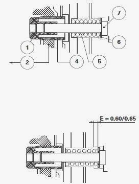
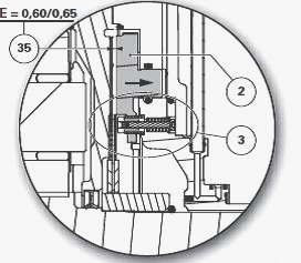
When the brake pistons (2) are pressurised by the block/valves assembly
(1) and the 50 kph hydraulic braking unit (5), they compress the brake
discs and drive the elements (4) (1) (7) and (6) of the return travel
limit mechanism. At the same time, the springs (5) compress by 0.60 to
0.65 mm depending on space E in order to fit the flat washers (6)
against the differential supports. Any wear to the brake discs (35) is
automatically corrected by the "tight" sliding of the brake discs (2) on
the Mecanindus pins (4).
Brakes inactive
When the brake pedal is released and the hydraulic pressure drops in the
brake piston chamber (2), the springs (5) decompress to the limit of E
(0.60 to 0.65 mm), thus separating the pistons (2) of the brake discs by
the same value.
Lubrication
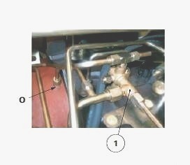
The brake discs are cooled during use by a flow of oil coming from the
lubrication system and flowing towards the hydraulic manifold (1) and
port O via the right-hand hydraulic cover plate. Oil flows between the
brake discs and pistons and lubricates their braking surfaces when they
are not in use. On Normal Duty trumpet housings, the brake discs are
lubricated by union R screwed directly onto each trumpet housing.
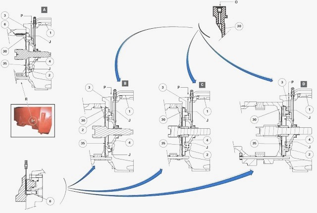
Parts list: (2) Brake piston (3) "O" ring (4) "O" ring
(6) Stop pins (30) Compartment or spacer (depending on type of trumpet
housing) (35) Brake disc, A - Brake mechanism without compartment (the
trumpet housing is thrust directly against the centre housing), B -
Brake mechanism with single compartment, C - Brake mechanism with sealed
compartment, D - Brake mechanism with spacer, J - Seals, O - Port for
lubrication of brake discs, P - Pressure emitted by the master
cylinder(s) (MF 6465, 6480 tractors) or a block/valve assembly (MF 6485,
6490 tractors), R - Union
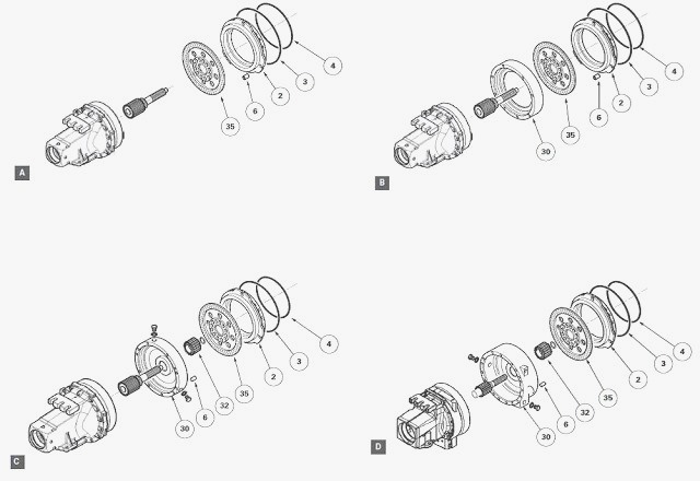
Parts list: (2) Brake piston (3) "O" ring (4) "O" ring
(6) Stop pins (30) Compartment or spacer (depending on type of trumpet
housing) (32) Hub (Heavy Duty sealed trumpet housing versions and
trumpet housings with composite final drive) (35) Brake disc, A - Brake
mechanism without compartment (the trumpet housing is thrust directly
against the centre housing), B - Brake mechanism with single
compartment, C - Brake mechanism with sealed compartment, D - Brake
mechanism with spacer
Massey Ferguson 6465, 6480, 6485, 6490 -
Removing and refitting a brake piston
Brake piston removal
Remove the trumpet housing(s).
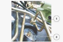
Disconnect the brake supply pipe (1) located above the centre housing
that comes from the brake master cylinder. For tractors fitted with
GTA1540 transmission (50 kph), the brake supply pipe (1) comes from the
block/valves (1) fitted to the cab's front bulkhead.
Using a manual hydraulic pump connected to the union (3), drive out the
piston (2) from the centre housing.
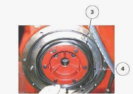
Remove the "O" rings (3) (4) fitted respectively on the centre housing
and the differential support. "O" rings J, located between the
differential supports and the centre housing, seal the brake piston
chambers.
If seal(s) is/are to be replaced, remove the differential support(s).
Brake piston refitting
Clean and check all components. Replace those that are defective. In
particular, check the wear on the brake plate, the sealed compartment or
the spacer (depending on type of trumpet housing). If removed, refit the
differential support(s) fitted with a new "O" ring J. Before the final
refitting of the piston (2), test fit the piston in the centre housing,
temporarily excluding the "O" rings (3) (4). This temporary fitting
allows you to check that the piston can move freely in its bore and on
its stop pins. During fitting, any friction points must be eliminated
and problem parts must be identified. Remove all impurities from the
piston chamber. Definitively refit the piston, but only after a
satisfactory test fitting has been carried out.
Lubricate the new "O" rings (3) (4) with clean transmission oil. Fit
them into their respective grooves (centre housing and differential
support). If possible, turn the brake piston so that the majority of the
lubricating ports around its rim are facing upwards (depending on piston
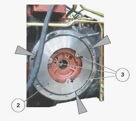
type). Fit the piston into the centre housing by aligning its pin
housings with the stop pins (6). Fit the piston (2) using a makeshift
tool and two screws V of suitable length. These two screws are tightened
gradually and alternately during the fitting process. For tractors
fitted with GTA1540 transmission (50 kph), carefully monitor the fitting
of the piston inside its return travel limit mechanism (3).
If necessary, fit by gently tapping with a plastic hammer in
diametrically opposed positions around the piston rim. The return travel
limit mechanism (3) means you have to push the brake pistons right back
to the bottom of their cavity (pushing the brake pistons is made easier
by gently unscrewing the centre housing and the bleed valves or pipes
coming from the block/valve assembly). In this way, the mechanism (3)
can once again return the brake pistons correctly if one or more of the
following components has been replaced: brake discs; brake plates,
compartment (single or sealed) or spacer (depending on the type of
trumpet housing); brake pistons and/or "O" rings (3) (4). Remove the
tool. Check that there are no seal fragments on the piston
circumference.
MF 6465, 6480, 6485, 6490 - Brake piston leak
test
The brake piston leak test can only be carried out correctly if the
pressure gauge and compressed air supply line are completely sealed.
Figure shows a simplified pressure gauge design. Other more complex
pressure gauges can also be used. Fit the tool used to retain the piston
(2) against the centre housing. Connect the pressure gauge to the union
(3). Supply the brake piston with compressed air at approximately 3 bar
to position the seals (3) (4) in their respective groove. Close the
valve. Disconnect the compressed air source. Open the valve.
Supply the system again at approximately 0.3-0.4 bar to test the
tightness of the seals (3) (4). Close the valve. Check that the pressure
gauge needle remains still for approximately one minute. Shut the
compressed air inlet when the test proves satisfactory. Remove: pressure
gauge; piston retaining tool. Reconnect the brake supply pipe. Refit the
trumpet housing (s). Thoroughly bleed the brake system. Road test the
main brakes. Check tightness of: trumpet housing seals; unions and the
pipes (brake supply and lubrication pipes).
Massey Ferguson 6485, 6490 - Disassembling,
reassembling and adjusting the return travel limit mechanism of the
brake piston
On MF 6485, 6490 tractor each brake piston (2) is assisted by a return
travel limit mechanism. This mechanism, which comprises three assemblies
(3), allows: piston to release itself from the brake disc by approx. 0.7
mm when the brakes are inactive; "drag" effect to be minimised.
The three assemblies (3) occupy an equidistant position on each
differential support S. An assembly comprises: M6 x 40 screw (7); flat
washer (6); spring (5); Mecanindus pin (4); shouldered nut with flat
sections (1); locking screw (8).
Return travel limit mechanism disassembly
The differential support(s) must be removed in order to disassemble the
brake piston's return travel limit mechanism. Remove: brake piston(s)
(2); differential support(s) S. Place the differential support(s) on a
workbench.
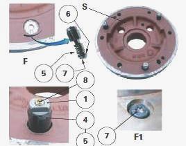
On faces F and F1 of differential support(s) S, remove an assembly (3)
including: locking screw (8); shouldered nut with flat sections (1)
(support the M6 screw (7)); Mecanindus pin (4); M6 screw (7); flat
washer (6); spring (5). Repeat step for the other two assemblies (3).
Return travel limit mechanism reassembly
Clean and check all components. Replace those that are defective.
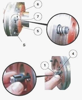
On faces F and F1 of differential support(s) S, refit: M6 screw (7);
flat washer (6); spring (5); Mecanindus pin (4); shouldered nut with
flat sections (1), with its thread lightly smeared with Loctite 243 or
equivalent.
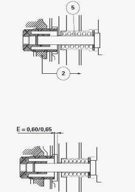
Settings
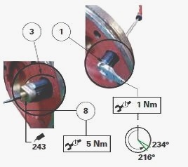
Adjust each assembly (3) of the brake piston's return travel limit
mechanism, proceeding as follows for each assembly: Tighten the
shouldered nut (1) with flat sections (M6, 100 pitch) to a torque of
approximately 1 Nm (spring coils almost joined).
Slacken off this nut between approximately half and three quarters of a
turn: this corresponds to an anti-clockwise rotation of 216° to 234° or
60% to 65% of a turn. By adjusting each assembly (3) of the return
travel limit mechanism in this way, a gap E of approx. 0.60 to 0.65 mm
is achieved between the piston (2) and the brake disc (35) when the main
brake is inactive.
________________________________________________________________________________
________________________________________________________________________________
________________________________________________________________________________________
 SPECS
SPECS LOADERS
 MAINTENANCE
 PROBLEMS
________________________________________________________________________________________
________________________________________________________________________________________
| MF TRACTORS SPECIFICATIONS |
 130
130 133
133 145
145 155
155 158
158________________________________________________________________________________________
 165
165 175
175 185
185 188
188 230
230________________________________________________________________________________________
 254
254 254S
254S 284S
284S 294
294 353
353________________________________________________________________________________________
 290
290 362
362 375
375 390
390 398
398________________________________________________________________________________________
 399
399 590
590 690
690 1010
1010 1030
1030________________________________________________________________________________________
 1020
1020 1150
1150 2620
2620 2640
2640 2645
2645________________________________________________________________________________________
 1540
1540 1736
1736 2660
2660 3065
3065 3095
3095________________________________________________________________________________________
 3650
3650 3680
3680 4255
4255 4355
4355 4370
4370________________________________________________________________________________________
 3630
3630 3635
3635 4245
4245 4445
4445 4609
4609________________________________________________________________________________________
 4710
4710 5435
5435 5475
5475 5610
5610 5711
5711________________________________________________________________________________________
 6150
6150 6170
6170 6180
6180 6270
6270 6290
6290________________________________________________________________________________________
 6445
6445 6499
6499 6614
6614 6713
6713 7465
7465________________________________________________________________________________________
 7495
7495 7614
7614 7622
7622 7715
7715 7726
7726________________________________________________________________________________________
 8210
8210 8270
8270 8650
8650 8727
8727 GC1705
________________________________________________________________________________________
| MF FRONT END LOADERS |
 1464 Loader
 1466 Loader
 1040 Loader
 1070 Loader
 905 Loader
________________________________________________________________________________________
 906 Loader
 915 Loader
 916 Loader
 921 Loader
 926 Loader
________________________________________________________________________________________
 931 Loader
 933 Loader
 936 Loader
 938 Loader
 939 Loader
________________________________________________________________________________________
 940 Loader
 941 Loader
 945 Loader
 946 Loader
 948 Loader
________________________________________________________________________________________
 949 Loader
 950 Loader
 951 Loader
 955 Loader
 956 Loader
________________________________________________________________________________________
 958 Loader
 960 Loader
 961 Loader
 965 Loader
 966 Loader
________________________________________________________________________________________
 968 Loader
 975 Loader
 976 Loader
 978 Loader
 985 Loader
________________________________________________________________________________________
 FL.3114 X
 FL.3419 X
 FL.3522
 FL.3615
 FL.3619
________________________________________________________________________________________
 FL.3817
 FL.3819
 FL.3823
 FL.4018
 FL.4121
 916X Loader
 921X Loader
 926X Loader
 931X Loader
 936X Loader
________________________________________________________________________________________
 941X Loader
 946X Loader
 951X Loader
 956X Loader
 988 Loader
________________________________________________________________________________________
 FL.4125
 FL.4227
 FL.4124
 FL.4220
 FL.4323
________________________________________________________________________________________
 FL.4327
 FL.4621
 FL.4624
 FL.4628
 FL.5033
________________________________________________________________________________________
 DL95 Loader
 DL100 Loader
 DL120 Loader
 DL125 Loader
 DL130 Loader
________________________________________________________________________________________
 DL135 Loader
 DL250 Loader
 DL260 Loader
 L90 Loader
 L100 Loader
________________________________________________________________________________________
 L105E Loader
 L210 Loader
 1014 Loader
 1016 Loader
 1462 Loader
________________________________________________________________________________________
 1525 Loader
 1530 Loader
 232 Loader
 838 Loader
 848 Loader
________________________________________________________________________________________
 246 Loader
 1036 Loader
 1038 Loader
 1080 Loader
 856 Loader
________________________________________________________________________________________
| MF TRACTORS MAINTENANCE |
 1010
1010 1020
1020 1030
1030 1035
1035 1040
1040________________________________________________________________________________________
 1045
1045 1080
1080 1085
1085 1120
1120 1125
1125________________________________________________________________________________________
 1140
1140 1160
1160 1165
1165 1180
1180 1190
1190________________________________________________________________________________________
 1205
1205 1210
1210 1215
1215 1220
1220 1225
1225________________________________________________________________________________________
 1230
1230 1233
1233 1235
1235 1240
1240 1260
1260________________________________________________________________________________________
| MF TRACTORS TROUBLESHOOTING | ||||
| 1652 | 1749 | 2620 | 2725 | 2805 |
| 3050 | 3120 | 3640 | 3709 | 4245 |
| 4455 | 5320 | 5455 | 5613 | 6150 |
| 6280 | 6480 | 6615 | 7618 | 7720 |