
________________________________________________________________________________
Massey Ferguson 6465, 6480, 6485 - Park Lock
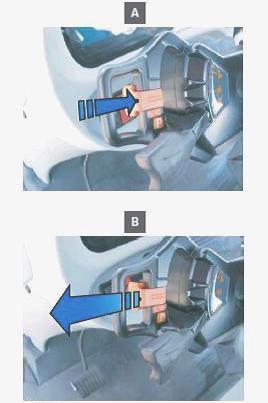
The Park Lock is a parking brake mechanism located above the GPA40 rear
axle. It is designed to immobilise the tractor in complete safety. The
Park Lock is easily controlled via a pushbutton located to the left of
and below the steering wheel. This pushbutton enables the operator to
select the Park Lock engaged position (A) or the disengaged position (B)
while seated in the operator's seat. The Park Lock mainly comprises
three parts: hydraulic part, electrical part, mechanical part.
Hydraulic part
The hydraulic part is located above the rear axle inside the Park Lock
unit (7)/cover plate (20) assembly. It comprises: two "O" rings (12) and
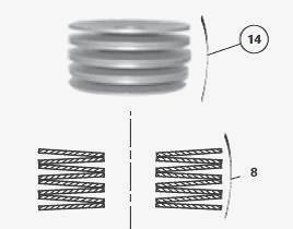
(13), piston (2), which is returned by a set of eight.
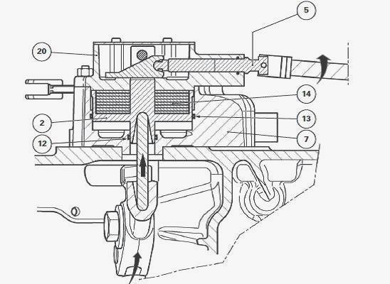
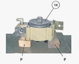
Belleville washers (14). The effect of the load exerted on the piston
(2) by the Belleville washers may be cancelled by fully screwing the
special hexagonal head screw (5). Cancelling the load exerted by the
Belleville washers is useful if: it is necessary to disassemble the Park
Lock, Hydraulic and/or electronic problem occurs, which hinders tractor
mobility.
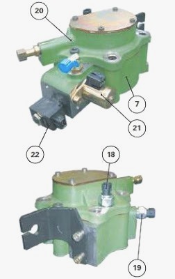
Electrical part
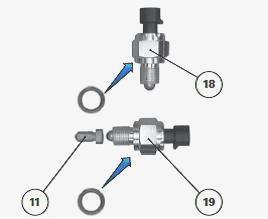
The electrical part comprises: two solenoid valves (21) and (22), two
switches (18) and (19). The solenoid valves and switches are screwed
onto the Park Lock unit (7) and the cover plate (20) respectively. They
are managed by the MF 6465, 6480, 6485, 6490 tractor's electronic system
and via the connectors.
Mechanical part
The mechanical part of the Park Lock uses the components and the
operating principle which are an extension of the hand brake mechanism.
Here is a reminder of the components used: Actuator lever, Discs,
Intermediate plates, Mechanism.

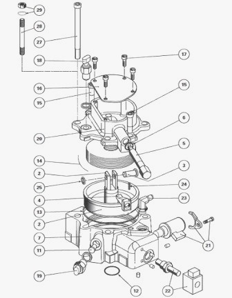
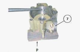
Parts list: (1) Park Lock (2) Piston (3) Pin (4) Wedge
(5) Special screw (manual disengagement) (6) "O" ring (7) Park Lock unit
(8) Actuator lever (9) Screw (10) Push rod (11) Pushrod (12) "O" ring
(13) "O" ring (14) Belleville washers (15) Screw (16) Cover plate (17)
Screw (18) Switch (19) Switch (20) Cover plate (21) Solenoid valve (22)
Solenoid valve (23) 17 or 21 bar union (24) Mecanindus pin (25) Circlip
(26) Tie rod (27) Screw (28) Stud (29) Washer/nut (M) Hand brake
mechanism

Massey Ferguson 6465, 6480, 6485, 6490 - Park
Lock Operation
Engaged position: mechanical action
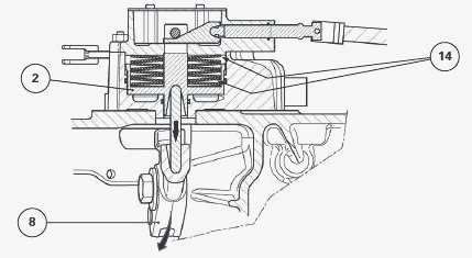
The movement of the piston (2) caused when the Belleville washers (14)
are released forces the actuator lever (8) to tilt, compressing the hand
brake discs splined in rotation with the pinion. The rear axle is then
blocked and the tractor is immobilised.
Disengaged position: hydraulic action
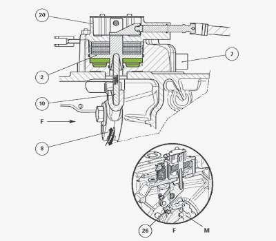
In this configuration, the Park Lock mechanism receives a 17 or 21 bar
oil supply via two different solenoid valves. The piston (2) then
compresses the Belleville washers and releases the push rod (10), the
mechanism (M) and the hand brake discs via the actuator lever (8) and
the hand brake tie rod (26). One of the two solenoid valves secures the
Park Lock disengaged position in the event of a fault. The principle
consists of maintaining the oil chamber of the piston (2) under pressure
by shutting off its return line. A switch screwed onto the cover plate
(20) and a second switch located on the Park Lock unit (7) check the
hand brake disc wear and operation of the Park-Lock respectively via
indicator lights. Each electrical component is controlled by the
tractor's electronic system.
MF 6465, 6480, 6485, 6490 - Manual
disengagement and engagement of the Park Lock
Manual disengagement
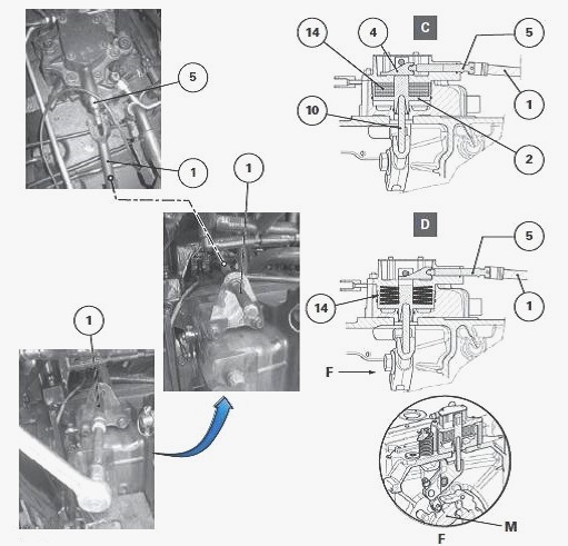
If manual disengagement is necessary - The Park Lock must be disengaged
manually: if the rear axle is to be removed for dismantling, to provide
tractor mobility in the event of a failure on the 17 or 21 bar hydraulic
system or a fault on the electronic management system.
Using the remote control (1) linked to the special screw (5) on the
cover plate, manually disengage the Park Lock by fully screwing in the
special screw (5) until it no longer turns.
Description of the mechanical reaction during manual disengagement -
When the special screw (5) is screwed in, the wedge (4) moves. This
beveled wedge mechanically pulls the piston (2) upwards, compressing the
set of Belleville washers (14). The load which had been applied to the
push rod (10) is cancelled. The mechanism (M) and the hand brake discs
are then released to make the tractor mobile.
Manual engagement
If for whatever reason the Park Lock has been disengaged, using the
remote control (1), completely unscrew the special screw (5) until it
comes into contact with a "hard" point. This procedure restores the Park
Lock original functions: disengagement (hydraulic function) and
engagement (mechanical function).
Massey Ferguson 6465, 6480, 6485, 6490 -
Removing and install the Park Lock unit
Remove the components restricting access to the Park Lock unit.
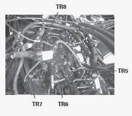
Disconnect the connectors (TR5) to (TR8) connected to the switches (18)
and (19) and the solenoid valves (21) and (22), marking them beforehand.
Disconnect the 17 or 21 bar supply pipe connected to the union (23).
Manually disengage the Park Lock.
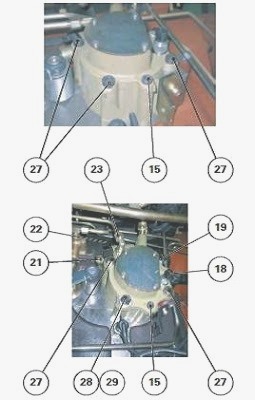
Removal
Remove the M12 screws (27) and the nut (29) (if fitted) but not the M10
screws (15). Separate and remove the Park Lock from the centre housing.
Recover the push rod (10) without allowing it to fall inside the centre
housing.
Install
Clean the mating face of the Park Lock on the centre housing and on the
unit (7). Smear the bottom end of the push rod (10) with Molykote type
grease or equivalent. Reinstall this rod into it compartment on the
actuator lever (8). Replace the two "O" rings providing the seal between
the Park Lock unit (7) and the centre housing. Smear the housing of the
piston (2) with Molykote type grease or equivalent. Position and refit
the Park Lock, fitting the upper end of the push rod (10) into the
compartment on the piston (2). Lightly smear the thread of the screws
(27) and the thread of the nut (29) (if fitted) with Loctite 542 or
equivalent. The thread of the screws and the stud (28) (if removed) must
be smeared with Loctite as their ends protrude inside the centre
housing. Tighten the screws (27) and the nut (29) to 100 to 130 Nm.
Reinstall the components which were taken off for hindering the removal
of the Park Lock unit. Restore the original functions to the Park Lock
(disengagement and engagement) by completely unscrewing the special
screw (5). Reconnect the 17 or 21 bar supply pipe connected to the union
(23). Reconnect the connectors (TR5) to (TR8) to the switches (18) and
(19) and the solenoid valves (21) and (22). Start the tractor engine.
Slowly move the tractor several meters over a track with a slight slope
and immediately place the shuttle lever back in the neutral position.
Before stopping the tractor, push the pushbutton to engage the Park-Lock
and carry out an initial test. When engaging the Park Lock, check that
the tractor is immobilized by noting a slight hesitation caused by the
transmission locking. Repeat the above procedure several times to
confirm that the Park Lock is operating correctly. While seated in the
operator's seat, move the tractor onto a track with a steeper slope.
Stop the engine and check: efficiency of the Park Lock, that the hand
brake is operating correctly. Check that there are no leaks in the
hydraulic system (union, mating face, switches and solenoid valves).
Massey Ferguson 6465, 6480, 6485, 6490 -
Disassembling and reassembling the Park Lock unit
Remove the Park Lock comprising the unit (7) and the cover plate (20).
Unscrew and remove: solenoid valves (21) and (22), switches (18) and
(19) fitted with their seal.
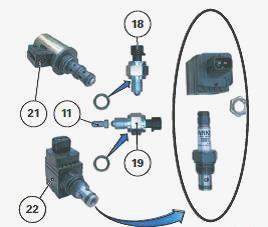
These switches are located on the cover plate (20) and on the unit (7)
respectively. Recover the pushrod (11). The pushrod (11) acts as a
transmission component between the switch (19) and the piston (2).
Park Lock unit disassembly
Completely unscrew the special screw (5) so that the Park Lock is in the
manual and as a result, the Belleville washers (14) are almost released.
Unscrew the screws (17). Release and remove the cover plate (16). Remove
the circlip (25) and the pin (3).
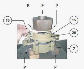
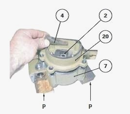
Place the Park Lock in a press, protecting the underside of the unit (7)
using two pieces of flexible protection (P). Also slide a flexible
protection (P) over the cover plate (20). Apply the hydraulic press ram
to the flexible protection (P) without exerting any force (F) on the
cover plate (20). Unscrew the screws (15). Slowly decompress the
hydraulic press ram to decompress the Belleville washers (14). Remove:
cover plate (20), Belleville washers (14), first noting their number and
positioning The eight Belleville washers are referenced in the spare
parts catalogue in the form of a kit.
On the cover plate (20): Drive out the spring pins (24). Completely
unscrew the special screw (5). Recover the wedge (4). Remove the "O"
ring (6) and discard it
Take out the piston (2) from the Park Lock unit (7). Remove and discard
the "O" rings (12) (13).
Park Lock unit reassembly
Clean: mating faces of the Park Lock unit (7); all parts. Using a jet of
compressed air or a flexible iron wire, check that the hydraulic
channels of the Park Lock unit (7) are not blocked. Check: that the
pushrod (11) for the switch (19) moves freely in its housing; that there
is a rivet fitted to the outer end of each hydraulic channel of the Park
Lock unit (7). Temporarily remove the seals (12) and (13) from the
piston (2). Test fit the latter inside the Park Lock unit (7). Check
that the piston moves freely inside its bore with no "hard" points.
Eliminate any impurities that may have become accidentally lodged inside
the chamber of the piston (2). Lubricate the seals (12) and (13) with
clean transmission oil. Install these seals into the grooves of the Park
Lock unit (7). Hold the piston (2) above the Park Lock unit (7),
positioning its flat section so that it is facing towards the return
port.
Install the piston (2), gently tapping its centre in a circular motion
using a plastic hammer. After fitting, check that there are no fragments
of seal around the piston. Lightly smear the upper mating face of the
Park-Lock unit with Loctite 5206 or equivalent. Reinstall the Belleville
washers (14).
Install and position the cover plate (20) on the Park Lock unit (7).
Test fit to check that the wedge (4) is correctly aligned with the
clevis of the piston (2). If the alignment is incorrect, correct it.
Place the Park Lock in a press, using the same protections that were
used for removal. Using the ram press, exert a moderate force (F) on the
cover plate (20) so as to compress the Belleville washers. As soon as
the cover plate (20) reaches the ParkLock unit (7), screw on and tighten
the two screws (15) to 57-77 Nm. Lubricate the "O" ring (6). Install it
into the groove of the cover plate (20). On the cover plate (20), screw
on the special screw (5) and fit the wedge (4) at the same time. Form a
wedge/special screw assembly using two new spring pins. Lightly smear
the upper mating face of the cover plate (20) with Loctite 5206 or
equivalent. Reinstall the cover plate (16). Tighten the screws (17) to a
torque of 12 to 16 Nm. Ensure that each switch is fitted with a new
seal.
Install: switch (18) onto the cover plate (20); pushrod (11) and the
switch (19) to the ParkLock unit (7). Tighten the switches to a torque
of 15-25 Nm. Install the solenoid valves (21) (22) in the same positions
as before disassembly. Tighten the following onto the solenoid valve
(22): spool to a torque of 18-20 Nm; solenoid to a torque of 4-5 Nm.
________________________________________________________________________________
________________________________________________________________________________
________________________________________________________________________________________
 SPECS
SPECS LOADERS
 MAINTENANCE
 PROBLEMS
________________________________________________________________________________________
________________________________________________________________________________________
| MF TRACTORS SPECIFICATIONS |
 130
130 133
133 145
145 155
155 158
158________________________________________________________________________________________
 165
165 175
175 185
185 188
188 230
230________________________________________________________________________________________
 254
254 254S
254S 284S
284S 294
294 353
353________________________________________________________________________________________
 290
290 362
362 375
375 390
390 398
398________________________________________________________________________________________
 399
399 590
590 690
690 1010
1010 1030
1030________________________________________________________________________________________
 1020
1020 1150
1150 2620
2620 2640
2640 2645
2645________________________________________________________________________________________
 1540
1540 1736
1736 2660
2660 3065
3065 3095
3095________________________________________________________________________________________
 3650
3650 3680
3680 4255
4255 4355
4355 4370
4370________________________________________________________________________________________
 3630
3630 3635
3635 4245
4245 4445
4445 4609
4609________________________________________________________________________________________
 4710
4710 5435
5435 5475
5475 5610
5610 5711
5711________________________________________________________________________________________
 6150
6150 6170
6170 6180
6180 6270
6270 6290
6290________________________________________________________________________________________
 6445
6445 6499
6499 6614
6614 6713
6713 7465
7465________________________________________________________________________________________
 7495
7495 7614
7614 7622
7622 7715
7715 7726
7726________________________________________________________________________________________
 8210
8210 8270
8270 8650
8650 8727
8727 GC1705
________________________________________________________________________________________
| MF FRONT END LOADERS |
 1464 Loader
 1466 Loader
 1040 Loader
 1070 Loader
 905 Loader
________________________________________________________________________________________
 906 Loader
 915 Loader
 916 Loader
 921 Loader
 926 Loader
________________________________________________________________________________________
 931 Loader
 933 Loader
 936 Loader
 938 Loader
 939 Loader
________________________________________________________________________________________
 940 Loader
 941 Loader
 945 Loader
 946 Loader
 948 Loader
________________________________________________________________________________________
 949 Loader
 950 Loader
 951 Loader
 955 Loader
 956 Loader
________________________________________________________________________________________
 958 Loader
 960 Loader
 961 Loader
 965 Loader
 966 Loader
________________________________________________________________________________________
 968 Loader
 975 Loader
 976 Loader
 978 Loader
 985 Loader
________________________________________________________________________________________
 FL.3114 X
 FL.3419 X
 FL.3522
 FL.3615
 FL.3619
________________________________________________________________________________________
 FL.3817
 FL.3819
 FL.3823
 FL.4018
 FL.4121
 916X Loader
 921X Loader
 926X Loader
 931X Loader
 936X Loader
________________________________________________________________________________________
 941X Loader
 946X Loader
 951X Loader
 956X Loader
 988 Loader
________________________________________________________________________________________
 FL.4125
 FL.4227
 FL.4124
 FL.4220
 FL.4323
________________________________________________________________________________________
 FL.4327
 FL.4621
 FL.4624
 FL.4628
 FL.5033
________________________________________________________________________________________
 DL95 Loader
 DL100 Loader
 DL120 Loader
 DL125 Loader
 DL130 Loader
________________________________________________________________________________________
 DL135 Loader
 DL250 Loader
 DL260 Loader
 L90 Loader
 L100 Loader
________________________________________________________________________________________
 L105E Loader
 L210 Loader
 1014 Loader
 1016 Loader
 1462 Loader
________________________________________________________________________________________
 1525 Loader
 1530 Loader
 232 Loader
 838 Loader
 848 Loader
________________________________________________________________________________________
 246 Loader
 1036 Loader
 1038 Loader
 1080 Loader
 856 Loader
________________________________________________________________________________________
| MF TRACTORS MAINTENANCE |
 1010
1010 1020
1020 1030
1030 1035
1035 1040
1040________________________________________________________________________________________
 1045
1045 1080
1080 1085
1085 1120
1120 1125
1125________________________________________________________________________________________
 1140
1140 1160
1160 1165
1165 1180
1180 1190
1190________________________________________________________________________________________
 1205
1205 1210
1210 1215
1215 1220
1220 1225
1225________________________________________________________________________________________
 1230
1230 1233
1233 1235
1235 1240
1240 1260
1260________________________________________________________________________________________
| MF TRACTORS TROUBLESHOOTING | ||||
| 1652 | 1749 | 2620 | 2725 | 2805 |
| 3050 | 3120 | 3640 | 3709 | 4245 |
| 4455 | 5320 | 5455 | 5613 | 6150 |
| 6280 | 6480 | 6615 | 7618 | 7720 |