
________________________________________________________________________________
Massey Ferguson 6465, 6480, 6485 - Rear axle pinion
Massey Ferguson 6465, 6480, 6485, 6490 -
Construction of rear axle pinion
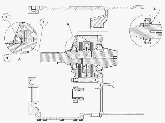
The crownwheel and pinion, driven by the gearbox output shaft, drives
the rear axle. The helical pinion is supported by two tapered roller
bearings fitted opposite one another. The bearing cone (7) is force
fitted onto the pinion. The bearing cup (2) is fitted tightly into the
cover plate (13). The bearing cup (10) is fitted tightly into the hand
brake unit. The bearing cone (1), freely mounted on the pinion, allows
the fitting of shims (3) required for shimming. The pinion supports the
4WD drive gear (17). Its position can be adjusted using the shim(s) (12)
fitted between the centre housing compartment and the hand brake unit
(15). The preload on the tapered roller bearings is obtained using the
shim(s) (3) fitted between the bearing cone (1) and the thrust washer
(4).
On MF 6465, 6480 tractor the pinion fitting and adjusting principle is
the same for the three current types of differential: 5" hydromechanical
differential; 5" multidisc differential; 7" multidisc differential.
On MF 6485, 6490 tractor the pinion fitting and adjusting principle is
the same for the two current types of differential: 5" multidisc
differential; 7" multidisc differential.
Lubrication
The oil is directed via a pipe to the axial channel and the radial holes
of the pinion to lubricate the hand brake mechanism and the tapered
roller bearings. The pipe is connected to the hydraulic manifold located
above the centre housing.
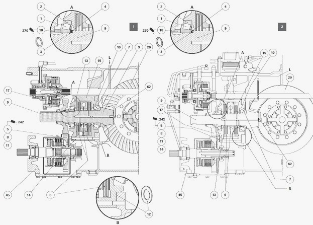
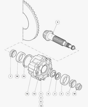
Parts lists: (1) Bearing cone (2) Bearing cup (3)
Shim(s) (4) Thrust washer (5) Allen screws (6) Hand brake mechanism (7)
Bearing cone (8) Allen screw (9) Pinion (10) Bearing cup (11) Washer
(12) Shim(s) (13) Hand brake unit cover plate (14) Locating pin (15)
Hand brake unit (17) 4WD drive gear (18) Nut (45) Centre housing (62)
Lubrication pipe
1 - GTA1040 transmission (MF 6465, 6480), 2 - GTA1540 transmission (MF
6485, 6490), A - Details, B - Details, L - Lubrication
Massey Ferguson 6465, 6480, 6485, 6490 -
Removing and refitting the pinion/hand brake unit assembly, removing and
refitting the pinion
Disconnect the tractor between the gearbox and the rear axle. Remove the
right-hand hydraulic cover plate (LS 110 l/min hydraulics). Remove the
left-hand hydraulic cover plate (LS 110 l/min hydraulics). Remove the
rear power take-off clutch.
Remove the 4WD shaft and its clutch: Remove the creeper unit control
mechanism (if fitted). Remove the circlip (5) and the thrust washer (2).
Visually note the position of the shim(s) (6) and remove it/them. Remove
the 4WD gear (17), sliding it along the pinion.
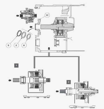
Removing the pinion/hand brake unit assembly
The pinion/hand brake unit assembly must be removed in order to work
efficiently on the pinion. Loosen and immobilise the nut (18). Using
special socket, turn the pinion clockwise to unlock the nut without
unscrewing it completely. The nut is not removed completely until the
hand brake unit is on the workbench for stripping. Unscrew the eight M12
hexagonal head screws (8). Remove their washers (11). Unscrew the M20
screw (1) from the hand brake actuator lever.
Unscrew the two M12 Allen screws (5) that attach the hand brake unit
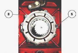
(15) to the centre housing compartment. Slide tool onto the pinion
splines. Moderately tighten the tool's three screws V in groove R of the
pinion.
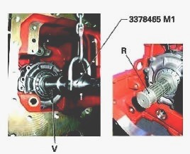
Sling the tool using a makeshift handling bar and a suitable lifting
device. Carefully pull the pinion/hand brake unit assembly forwards and
release it from the centre housing.
Recover the shims (12) (internal diameter approx. 175 mm) on the hand
brake unit assembly. The shims inserted between the hand brake unit and
the centre housing compartment are used for adjusting the taper
distance. Separate the sling and tool from the pinion/hand brake unit
assembly.
Massey Ferguson 6465, 6480, 6485, 6490 -
Disassembling the pinion
Place the pinion/hand brake unit assembly vertically on the workbench.
Completely unscrew the nut (18) and discard it. Remove: tapered roller
bearing cone (1); shim(s) (3); thrust washer (4), marking its position.
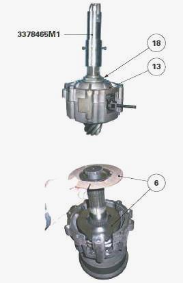
Remove the cover plate (13) and the hand brake mechanism (6). Remove the
pinion, separating it from the hand brake unit (15). If necessary,
extract the tapered roller bearing cone (7) from the pinion. Remove:
bearing cup (2) from the cover plate (13), locating pin (14) from the
hand brake unit (15).
Reassembling the pinion
The shimming with preload on the pinion's tapered roller bearings and
the adjustment of the pinion/hand brake unit assembly position must be
checked after one or more of the following parts are replaced: centre
housing; pinion; head bearing (tapered bearing cone (7) and the cup
(10)); hand brake unit (15); unit cover plate (13); end bearing (tapered
bearing cone (1) and cup (2)). Clean and check all components. Replace
those that are defective.
If disassembled, use a press and a suitable fixture to fit the tapered
roller bearing cone (7) against the pinion shoulder. Fit the tapered
roller bearing cone (10) against the shoulder of the hand brake unit.
Check that the elements are properly supported by their respective
bases. Place the hand brake unit (15) vertically on the workbench,
having fitted the pinion beforehand. Reassemble the hand brake mechanism
inside the unit (15). Fit the tapered roller bearing cup (2) against the
cover plate shoulder (13). Fit the cover plate (13) after checking that
the locating pin (14) is present.
On the pinion, slide the thrust washer (4) against shoulder E together
with the shim(s) (3) used to preload the tapered roller bearings. The
shim(s) (3) required for shimming by preloading the tapered roller
bearings (1) (2) and (7) (10) must be inserted between the thrust washer
(4) and the tapered roller bearing cone (1). Fit the tapered roller
bearing cone (1) after lubricating the cone with clean transmission oil.
Tighten the new nut (18) without locking it. If necessary, carry out the
shimming with preload on the pinion tapered roller bearings and the
adjustment of the position of the pinion/hand brake unit assembly. The
new nut (18) will be definitively locked when the pinion/hand brake unit
assembly (15) is refitted to the centre housing.
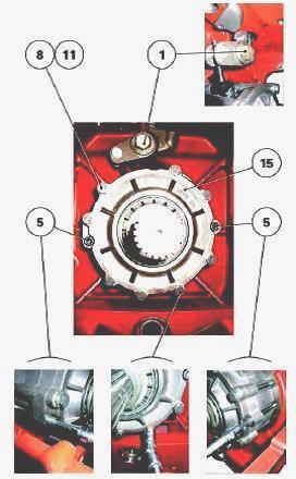
MF 6465, 6480, 6485, 6490 - Refitting the
pinion/hand brake unit assembly
Clean and check all components. Replace those that are defective.
Position the shim(s) (12) on the fitting area of the hand brake unit
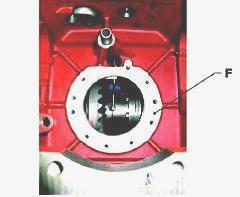
(15). Refit the pinion/hand brake unit assembly against face F of the
centre housing compartment. During the refitting process, refit the hand
brake actuator lever at the same time.
Press the hand brake unit towards the centre housing compartment, in
preparation for fitting. Align the three fixing holes on the hand brake
unit with the compartment holes by screwing a guide stud into a tapped
hole located at the top of the centre housing. Clean the thread of the
screws (5) (8) and lightly smear with Loctite 242 or equivalent. Screw
in the Allen screws (5). Screw in the hexagonal head screws (8) fitted
with their washers (11) while removing the guide stud at the same time.
Tighten the diametrically opposed screws (5) (8) uniformly and
step-by-step to a tightening torque of 100-130 Nm. This tightening
method ensures that the hand brake unit (15) is fitted gradually and
smoothly into the centre housing compartment and that the shim(s) (12)
are applied appropriately. Adjust the hand brake mechanism. Degrease the
threads of the new nut (18) and the pinion. Lightly smear the thread of
the nut with Loctite 270 or equivalent. Lock the nut. Using socket ref.
3378119 M1, turn the pinion anti-clockwise to a tightening torque of
200-250 Nm. Ensure that the torque wrench is properly positioned in
order to obtain the correct tightening torque for the nut. Remove tools.
Using a suitable punch, lock the nut by bending its collar, without
breaking it, into the three pinion grooves. Slide the 4WD gear (17) over
the pinion splines. Fit the following, observing the correct fitting
order: shim(s) (6) then thrust washer (2) then circlip (5). Check the
axial clearance of the 4WD gear (17): it should be between 0 and 0.55
mm. As far as possible, shim to the minimum tolerance. Refit: left-hand
hydraulic cover plate (LS 110 l/min equipment); right-hand hydraulic
cover plate (LS 110 l/min equipment); creeper unit control mechanism (if
fitted); 4WD clutch and its shaft; power take-off clutch. Reconnect the
tractor between the gearbox and the rear axle.
________________________________________________________________________________
________________________________________________________________________________
________________________________________________________________________________________
 SPECS
SPECS LOADERS
 MAINTENANCE
 PROBLEMS
________________________________________________________________________________________
________________________________________________________________________________________
| MF TRACTORS SPECIFICATIONS |
 130
130 133
133 145
145 155
155 158
158________________________________________________________________________________________
 165
165 175
175 185
185 188
188 230
230________________________________________________________________________________________
 254
254 254S
254S 284S
284S 294
294 353
353________________________________________________________________________________________
 290
290 362
362 375
375 390
390 398
398________________________________________________________________________________________
 399
399 590
590 690
690 1010
1010 1030
1030________________________________________________________________________________________
 1020
1020 1150
1150 2620
2620 2640
2640 2645
2645________________________________________________________________________________________
 1540
1540 1736
1736 2660
2660 3065
3065 3095
3095________________________________________________________________________________________
 3650
3650 3680
3680 4255
4255 4355
4355 4370
4370________________________________________________________________________________________
 3630
3630 3635
3635 4245
4245 4445
4445 4609
4609________________________________________________________________________________________
 4710
4710 5435
5435 5475
5475 5610
5610 5711
5711________________________________________________________________________________________
 6150
6150 6170
6170 6180
6180 6270
6270 6290
6290________________________________________________________________________________________
 6445
6445 6499
6499 6614
6614 6713
6713 7465
7465________________________________________________________________________________________
 7495
7495 7614
7614 7622
7622 7715
7715 7726
7726________________________________________________________________________________________
 8210
8210 8270
8270 8650
8650 8727
8727 GC1705
________________________________________________________________________________________
| MF FRONT END LOADERS |
 1464 Loader
 1466 Loader
 1040 Loader
 1070 Loader
 905 Loader
________________________________________________________________________________________
 906 Loader
 915 Loader
 916 Loader
 921 Loader
 926 Loader
________________________________________________________________________________________
 931 Loader
 933 Loader
 936 Loader
 938 Loader
 939 Loader
________________________________________________________________________________________
 940 Loader
 941 Loader
 945 Loader
 946 Loader
 948 Loader
________________________________________________________________________________________
 949 Loader
 950 Loader
 951 Loader
 955 Loader
 956 Loader
________________________________________________________________________________________
 958 Loader
 960 Loader
 961 Loader
 965 Loader
 966 Loader
________________________________________________________________________________________
 968 Loader
 975 Loader
 976 Loader
 978 Loader
 985 Loader
________________________________________________________________________________________
 FL.3114 X
 FL.3419 X
 FL.3522
 FL.3615
 FL.3619
________________________________________________________________________________________
 FL.3817
 FL.3819
 FL.3823
 FL.4018
 FL.4121
 916X Loader
 921X Loader
 926X Loader
 931X Loader
 936X Loader
________________________________________________________________________________________
 941X Loader
 946X Loader
 951X Loader
 956X Loader
 988 Loader
________________________________________________________________________________________
 FL.4125
 FL.4227
 FL.4124
 FL.4220
 FL.4323
________________________________________________________________________________________
 FL.4327
 FL.4621
 FL.4624
 FL.4628
 FL.5033
________________________________________________________________________________________
 DL95 Loader
 DL100 Loader
 DL120 Loader
 DL125 Loader
 DL130 Loader
________________________________________________________________________________________
 DL135 Loader
 DL250 Loader
 DL260 Loader
 L90 Loader
 L100 Loader
________________________________________________________________________________________
 L105E Loader
 L210 Loader
 1014 Loader
 1016 Loader
 1462 Loader
________________________________________________________________________________________
 1525 Loader
 1530 Loader
 232 Loader
 838 Loader
 848 Loader
________________________________________________________________________________________
 246 Loader
 1036 Loader
 1038 Loader
 1080 Loader
 856 Loader
________________________________________________________________________________________
| MF TRACTORS MAINTENANCE |
 1010
1010 1020
1020 1030
1030 1035
1035 1040
1040________________________________________________________________________________________
 1045
1045 1080
1080 1085
1085 1120
1120 1125
1125________________________________________________________________________________________
 1140
1140 1160
1160 1165
1165 1180
1180 1190
1190________________________________________________________________________________________
 1205
1205 1210
1210 1215
1215 1220
1220 1225
1225________________________________________________________________________________________
 1230
1230 1233
1233 1235
1235 1240
1240 1260
1260________________________________________________________________________________________
| MF TRACTORS TROUBLESHOOTING | ||||
| 1652 | 1749 | 2620 | 2725 | 2805 |
| 3050 | 3120 | 3640 | 3709 | 4245 |
| 4455 | 5320 | 5455 | 5613 | 6150 |
| 6280 | 6480 | 6615 | 7618 | 7720 |