
________________________________________________________________________________
Massey Ferguson 6465, 6480, 6485 - Rear PTO
Massey Ferguson 6465, 6480, 6485 - Rear PTO operation
The housing installed to the rear of the GPA40 rear axle contains all
the rear mechanical power take-off components. These components rest on
the tapered roller bearings, the bearing cups of which are on the rear
PTO housing and its removable compartment and fitted freely and firmly
respectively.
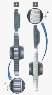
Profile P of the 1000 rpm gear train teeth (driving and driven gears)
differs according to the type of tractor and the transmission equipment
fitted: Power Boost. The rear PTO is independent for MF 6465, 6480,
6485, 6490 tractor except for the Ground speed PTO version, which uses
the tractor's forward speed for operation. The Ground speed PTO is
fitted to tractors as an option.
The rear PTO can be divided into four sections:
1. Clutch - The clutch is located on the upper PTO shaftline and at the
front of the centre housing. It is supported by two ball bearings fitted
in a support mounted on the centre housing.
2. Upper shaftline - The upper shaftline of the rear PTO transmits the
engine speed to the driving gears located inside the rear housing of the
PTO via the clutch and a series of three shafts. The tapered roller
bearings supporting - the driving gear shaft are shimmed with a
clearance using shim(s) inserted between the front bearing cup and the
removable compartment.
3. Lower shaftline - The lower shaftline of the rear PTO is supported by
two tapered roller bearings fitted respectively in the rear PTO housing
and in the removable compartment. The tapered roller bearings are held
in position by a nut screwed onto the front end of the output shaft. The
preload shimming of the tapered roller bearings is carried out using
shim(s) inserted between the front bearing cup and the removable
compartment. The output shaft is sealed by a lip seal fitted into the
rear PTO housing. The output shaft is fitted with an interchangeable end
fitting which may be: of varying length; fitted with 6, 20 or 21
splines. The specifications of the output shaft depend on the type of
implement to be driven and on the rotational speed to be observed.
4. Power take-off brake - The rear PTO is fitted with a brake housed
inside the rear housing opposite the 1000 rpm driven gear. The rear PTO
brake gradually slows down the output shaft inertia until it stops
completely when the rear PTO clutch is disengaged. It is also used to
immobilise the gear trains (driving and driven gears) to prevent the
"drag" effect.
Massey Ferguson 6465, 6480, 6485 - Lubrication of the rear PTO
components
The clutch - The parts inside the rear PTO clutch are lubricated under
pressure via a pipe located above and in front of the centre housing.
The upper shaftline - An external pipe carries the lubrication oil under
pressure to the upper shaftline of the rear PTO. The flow of oil to the
driving gears and the tapered roller bearings is controlled by two
restrictors and an oil deflector located respectively in the rear
housing of the PTO (power take-off) and in the upper shaftline.
The lower shaftline - The lower shaftline of the rear PTO is supplied
with pressurised oil carried by a pipe to the front end of the output
shaft. This oil lubricates the rear bearing and the splines of the
output shaft driven gears.
The power take-off brake - The PTO brake is not lubricated under
pressure. Just the splashing of oil from the rear PTO housing is
sufficient to lubricate the friction washer, which is in contact with
the machined face of the 1000 rpm driven gear when the rear PTO (power
take-off) line is locked.
Massey Ferguson 6465, 6480, 6485 Rear PTO - Layout of the main components and
kinematics
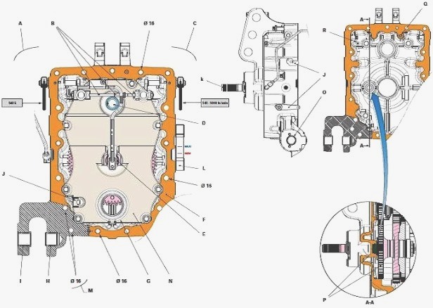
MF 6465, 6480 Tractors installed with GTA1040 transmission
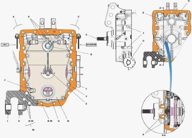
MF 6485, 6490 Tractors installed with GTA1540 transmission
The lower fixture of the rear PTO housing on MF 6485, 6490 tractors
installed with GTA1540 transmission is reinforced by fitting six 20 mm
diameter screws instead of the four 16 mm diameter screws used on MF
6465, 6480 tractors fitted with GTA1040 transmission.
Parts list: A - 540E control mechanism, B - Interlock
mechanism/adjustable sleeve assembly, C - 540-1000 rpm control
mechanism, D - Upper PTO shaftline, E - Lower PTO shaftline, F - Rear
housing of the PTO (power take-off), G - Ground Speed PTO shaftline (optional), H -
Smooth ring, I - Shouldered ring, J - Ground Speed PTO control mechanism
(optional), K - Interchangeable end fitting, L - Transmission oil level
gauge, M - Rear housing standard fixing (1040), M - Rear housing
reinforced fixing (1540), N - Removable compartment, O - Fixing for
linkage effort sensor, P - PTO brake mechanism and 1000 rpm driven gear,
Q - Pin, R - Restrictor D=1 mm
2-speed PTO with coupler control
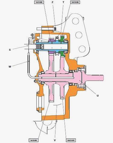
Parts list: S - Power take-off driving shaft, T - 540 and 1000 rpm speed
selection coupler, U - Output shaft with interchangeable end fitting, V
- Driven gear train, W - Lubrication pipe, Z - Driving gear train
Kinematics
The 540 and 1000 rpm driving gears of the upper shaftline have spur cut
teeth and are constantly meshed with the respective 540-1000 rpm gears
of output shaft U. They drive the output shaft at a speed of 540 or 1000
rpm depending on the position of selection coupler T.
3-speed PTO with coupler control
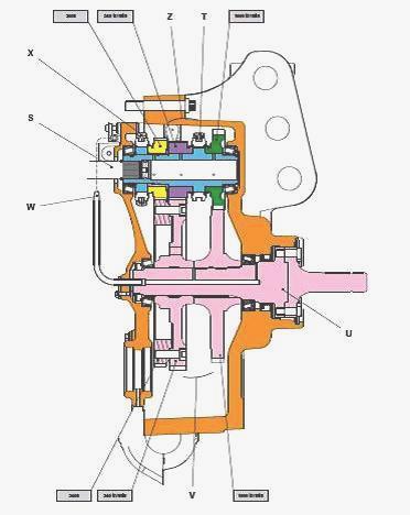
Parts list: S - Power take-off driving shaft, T - 540 and 1000 rpm speed
selection coupler, U - Output shaft with interchangeable end fitting, V
- Driven gear train, W - Lubrication pipe, X - 540E selection coupler, Z
- Driving gear train
Kinematics
The 540-1000 rpm and 540E gears have spur cut teeth and are constantly
meshed with the respective 540-1000 rpm and 540E gears of output shaft
U. They drive the output shaft at a speed of 540-1000 rpm or 540E
depending on the position of selection couplers T and X. The 540E speed
is an economic ratio. It is obtained via an additional gear and a
coupler fitted to the front end of the driving gear train. When
selection coupler X is engaged, two interlock mechanisms joined by an
adjustable sleeve prevent selection coupler T from engaging. When a
coupler is engaged, the interlock mechanisms lock the passive coupler in
neutral at the control rod locking groove.
Ground Speed PTO with coupler control
Ground Speed PTO is fitted to tractors as an option.
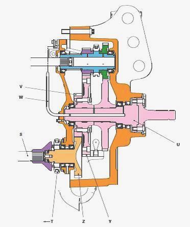
Parts list: S - Power take-off driving shaft, T - Ground Speed PTO selection
coupler, U - Output shaft with interchangeable end fitting, V - Driven
gear (attached to gear Y by a screw), W - Lubrication pipe, Y - Driven
gear, Z - Driving gear
Kinematics
The Ground Speed PTO driving and driven gears have spur cut teeth and
are constantly meshed. They drive output shaft U at a speed proportional
to the tractor's forward speed when selection coupler T is moved to the
left. Ground Speed PTO is activated when the 540-1000 rpm PTO is deactivated.
The rotational movement of the Ground Speed PTO is transmitted via the
rear axle pinion (crown wheel and pinion) and a gear train 4 wheel drive
(4WD) at output shaft U via a driving shaft S and two gears Z and V.
________________________________________________________________________________
________________________________________________________________________________
________________________________________________________________________________________
 SPECS
SPECS LOADERS
 MAINTENANCE
 PROBLEMS
________________________________________________________________________________________
________________________________________________________________________________________
| MF TRACTORS SPECIFICATIONS |
 130
130 133
133 145
145 155
155 158
158________________________________________________________________________________________
 165
165 175
175 185
185 188
188 230
230________________________________________________________________________________________
 254
254 254S
254S 284S
284S 294
294 353
353________________________________________________________________________________________
 290
290 362
362 375
375 390
390 398
398________________________________________________________________________________________
 399
399 590
590 690
690 1010
1010 1030
1030________________________________________________________________________________________
 1020
1020 1150
1150 2620
2620 2640
2640 2645
2645________________________________________________________________________________________
 1540
1540 1736
1736 2660
2660 3065
3065 3095
3095________________________________________________________________________________________
 3650
3650 3680
3680 4255
4255 4355
4355 4370
4370________________________________________________________________________________________
 3630
3630 3635
3635 4245
4245 4445
4445 4609
4609________________________________________________________________________________________
 4710
4710 5435
5435 5475
5475 5610
5610 5711
5711________________________________________________________________________________________
 6150
6150 6170
6170 6180
6180 6270
6270 6290
6290________________________________________________________________________________________
 6445
6445 6499
6499 6614
6614 6713
6713 7465
7465________________________________________________________________________________________
 7495
7495 7614
7614 7622
7622 7715
7715 7726
7726________________________________________________________________________________________
 8210
8210 8270
8270 8650
8650 8727
8727 GC1705
________________________________________________________________________________________
| MF FRONT END LOADERS |
 1464 Loader
 1466 Loader
 1040 Loader
 1070 Loader
 905 Loader
________________________________________________________________________________________
 906 Loader
 915 Loader
 916 Loader
 921 Loader
 926 Loader
________________________________________________________________________________________
 931 Loader
 933 Loader
 936 Loader
 938 Loader
 939 Loader
________________________________________________________________________________________
 940 Loader
 941 Loader
 945 Loader
 946 Loader
 948 Loader
________________________________________________________________________________________
 949 Loader
 950 Loader
 951 Loader
 955 Loader
 956 Loader
________________________________________________________________________________________
 958 Loader
 960 Loader
 961 Loader
 965 Loader
 966 Loader
________________________________________________________________________________________
 968 Loader
 975 Loader
 976 Loader
 978 Loader
 985 Loader
________________________________________________________________________________________
 FL.3114 X
 FL.3419 X
 FL.3522
 FL.3615
 FL.3619
________________________________________________________________________________________
 FL.3817
 FL.3819
 FL.3823
 FL.4018
 FL.4121
 916X Loader
 921X Loader
 926X Loader
 931X Loader
 936X Loader
________________________________________________________________________________________
 941X Loader
 946X Loader
 951X Loader
 956X Loader
 988 Loader
________________________________________________________________________________________
 FL.4125
 FL.4227
 FL.4124
 FL.4220
 FL.4323
________________________________________________________________________________________
 FL.4327
 FL.4621
 FL.4624
 FL.4628
 FL.5033
________________________________________________________________________________________
 DL95 Loader
 DL100 Loader
 DL120 Loader
 DL125 Loader
 DL130 Loader
________________________________________________________________________________________
 DL135 Loader
 DL250 Loader
 DL260 Loader
 L90 Loader
 L100 Loader
________________________________________________________________________________________
 L105E Loader
 L210 Loader
 1014 Loader
 1016 Loader
 1462 Loader
________________________________________________________________________________________
 1525 Loader
 1530 Loader
 232 Loader
 838 Loader
 848 Loader
________________________________________________________________________________________
 246 Loader
 1036 Loader
 1038 Loader
 1080 Loader
 856 Loader
________________________________________________________________________________________
| MF TRACTORS MAINTENANCE |
 1010
1010 1020
1020 1030
1030 1035
1035 1040
1040________________________________________________________________________________________
 1045
1045 1080
1080 1085
1085 1120
1120 1125
1125________________________________________________________________________________________
 1140
1140 1160
1160 1165
1165 1180
1180 1190
1190________________________________________________________________________________________
 1205
1205 1210
1210 1215
1215 1220
1220 1225
1225________________________________________________________________________________________
 1230
1230 1233
1233 1235
1235 1240
1240 1260
1260________________________________________________________________________________________
| MF TRACTORS TROUBLESHOOTING | ||||
| 1652 | 1749 | 2620 | 2725 | 2805 |
| 3050 | 3120 | 3640 | 3709 | 4245 |
| 4455 | 5320 | 5455 | 5613 | 6150 |
| 6280 | 6480 | 6615 | 7618 | 7720 |