
________________________________________________________________________________
Massey Ferguson 6465, 6480, 6485, 6490 - Rear PTO clutch
Massey Ferguson 6465, 6480, 6485, 6490 Rear
PTO clutch operation
Rear PTO clutch engagement and disengagement are controlled electrically
by a proportional solenoid valve, which is itself controlled by the
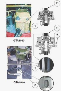
tractor's electronic system. The clutch, located at the front and in the
upper section of the centre housing, controls the operation of the rear
PTO. It is connected in rotation to the engine flywheel via a vibration
damper fixed to the flywheel and a line comprising two shafts.
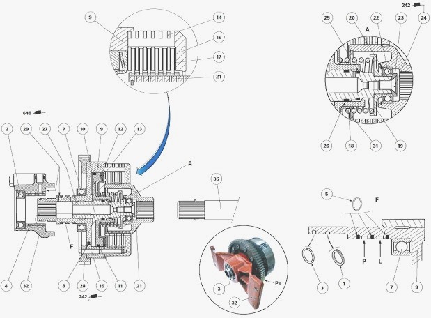
It consists of a unit (9) supported by two ball bearings (2) (7) centred
in a support (32) fitted to the centre housing. The sleeve (27) supports
the ball bearing (22), the drive hub (21) and the piston (10). The
clutch housing (9) comprises: at the front, a helical gear (28), fixed
using screws, which transmits the movement to the hydraulic pumps. For
tractors equipped with GTA1540 transmission, gear P1 (28) has spur cut
teeth. It is also fixed using screws; at the rear, a bell housing (15)
with a set of discs (17) and intermediate plates (14). A sealing ring
(3) minimises leakage between the rear end of the gearbox upper shaft
and the clutch unit (9).
Clutch engaged position
The rear PTO clutch is supplied via the 17 bar (GTA1040 tractor
transmission) or 21 bar (tractors equipped with GTA1540 transmission)
low pressure hydraulic system and via a proportional solenoid valve
fitted to the right-hand hydraulic cover plate. A transfer pipe
hydraulically links the right-hand hydraulic cover plate and the clutch
support (32). Pressurised oil enters the unit (9) through hole P and
then flows to the rear of the piston (10) via an internal channel. It
pushes the piston, which compresses the discs (17) and the intermediate
plates (14). The intermediate plates are attached to the bell housing
(15) by lugs. The discs are splined to the hub (21). The movement is
then transmitted to the rear PTO driving gears via a shaft (35). When
the clutch is engaged, the PTO brake piston located in the rear housing
is at rest and releases the lower PTO shaftline.
Clutch disengaged position
If the solenoid valve is no longer supplying the rear PTO clutch, the
piston (10) is returned against the unit (9) by the spring (18). The oil
in the piston chamber is directed to the return by the solenoid valve.
The valve ball (8) leaves its seat, thus assisting the decompression of
the chamber.
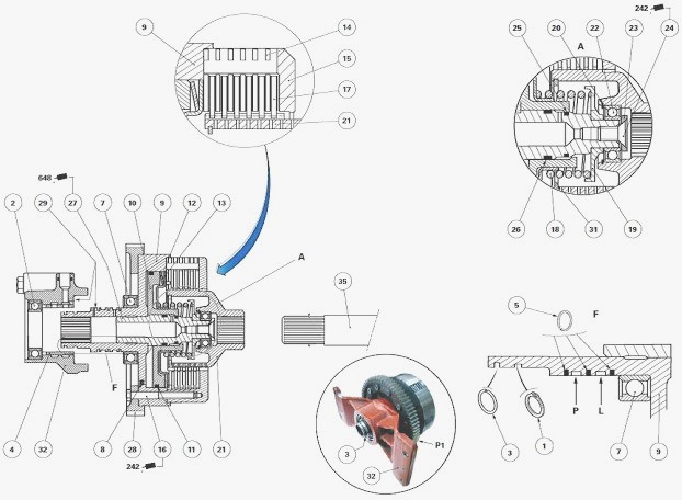
Parts list: (1) Circlip (2) Ball bearings (3) Sealing
ring (4) Ring (5) Seal rings (7) Ball bearing (8) Valve (9) Clutch unit
(10) Piston (11) "O" ring (12) Belleville progressivity washers (13)
Spring support (14) Intermediate plates (15) Bell housing (16) Screw
(17) Discs (18) Spring (19) Spring seat (20) Snap ring (21) Drive hub
(22) Ball bearing (23) Chamfered washer (24) Countersunk screw (25) "O"
ring (26) "O" ring (27) Sleeve (28) Gear (29) Restrictors (31) Circlip
used for oil deflector (32) Clutch support (35) Shaft, A - Details, L -
Lubrication groove, P - Low pressure groove (17 or 21 bar), P1 - Gear
with spur cut teeth (GTA1540 tractor transmission)
Massey Ferguson 6465, 6480, 6485, 6490 -
Disassembling the PTO clutch
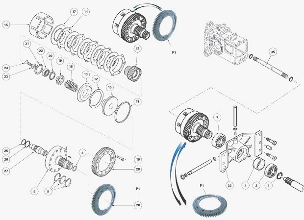
Remove the clutch. Separate the clutch from its support. Remove the seal
rings (5). If necessary, discard them. Remove the screws (16). Remove:
bell housing (15); discs (17) and intermediate plates (14); drive gear
(28). Secure the front part of the clutch unit (9) in a vice fitted with
protective jaws. Remove the screw (24), using a makeshift tool to hold
back the spring (18). Remove the chamfered washer (23).
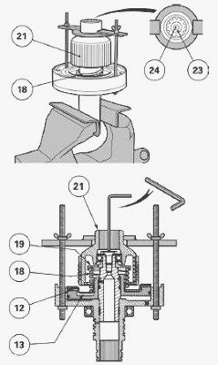
Gradually release the spring (18) using the tool. Remove: hub (21); seat
(19); spring (18); support (13); Belleville progressivity washer (12).
Remove the piston (10) by firmly striking the clutch unit against the
wooden edge of a workbench or failing that, against block of a similar
nature. Remove and discard the "O" rings (11), (25) and (26). If
necessary, remove the circlip (31) (oil deflector). Extract or drive
out: bearing (2) on the support (32); bearing (7) on the unit (9),
visually noting the positioning of its sealed face; bearing (22) by
first removing the snap ring (20).
Massey Ferguson 6465, 6480, 6485, 6490 -
Reassembling the PTO clutch
Clean and check all components. Replace those that are defective. Check
the clearance of the valve ball (8) by vertically and rapidly shaking
the unit (9): rattling against the unit should be heard. If removed,
press fit the sleeve (27) in the unit (9). Before fitting, the fitted
section of the sleeve (27) must be lightly smeared with Loctite 648 or
equivalent. Clean off any excess Loctite. Check that the various
hydraulic ports are not obstructed after the fitting process. Using a
press and a suitable fixture in contact with the external surface of the
bearing (22), Install the bearing up to the shoulder of the hub (21).
Install the snap ring (20).
Position the sealed face of the bearing (7) towards the unit (9). Using
a press and a suitable fixture in contact with the internal surface of
the bearing (7), Install this bearing against the unit (9). Using a
press and a suitable fixture in contact with the external surface of the
bearing (2), Install the bearing up to the shoulder of the support (32).
After fitting, check that the bearings turn correctly. Install the
circlip (31) (oil deflector). Lubricate and Install the new seals (11)
(25) (26) on the sleeve (27) and piston (10) respectively. Install the
piston using a soft hammer, checking during the fitting process that
there are no fragments of seal on its rim.
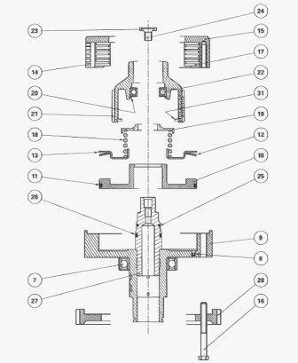
Reinstall: Belleville progressivity washer (12); support (13); spring
(18); spring seat (19). Reinstall the pre-assembled hub (21), using the
tool used during disassembly to progressively compress the spring (18).
Secure the front part of the clutch unit (9) in a vice fitted with
protective jaws. Position the chamfer of the washer (23). Position this
washer in the drive hub (21). Lightly smear the thread of the screw (24)
with Loctite 270 or equivalent. Tighten this screw to a torque of 24-28
Nm. If the clutch discs (17) have been replaced, the new discs must be
soaked for approximately one hour in clean transmission oil.
Stack the new or reused discs and intermediate plates (14), starting
with an intermediate plate against the spring support (13). Install the
discs and intermediate plates alternately until the number removed
during disassembly is reached. Reinstall the bell housing (15) and the
drive gear (28) in the correct position. Lightly smear the thread of the
screws (16) with Loctite 242 or equivalent. Tighten these screws to
25.5-34.5 Nm. Install the seal rings (5). Reconnect the clutch and its
support. Install the assembly.
Massey Ferguson 6465, 6480, 6485, 6490 - PTO
clutch removing and install
To remove the rear PTO clutch, the tractor must be separated between the
gearbox and the rear axle.
Disconnect the tractor between the gearbox and the rear axle. Remove the
right-hand hydraulic cover plate. Remove the 17-bar hydraulic pipe (MF
6465, 6480 tractor) or 21-bar hydraulic pipe (MF 6485, 6490 tractor).
This pipe is located at the top right of the mating face of the
right-hand hydraulic cover plate on the centre housing. It links the
clutch and the right-hand hydraulic cover plate.
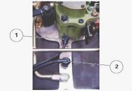
Remove: union and the transfer pipe, which are fitted above the centre
housing and are used to lubricate the clutch; sensor (1) (MF 6465,
6480); sensors (1) and (2) (MF 6485, 6490). The sensor (1) (output
speed) and sensor (2) (input speed) are located above the centre
housing. They inform the tractor's electronic system of the clutch
behaviour.
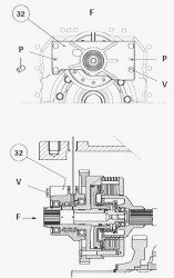
Removal
Unscrew the four M12 V screws. These screws fix the support (32) of the
rear PTO clutch to the centre housing. Using a suitable tool and the
original PTO shaft, remove the clutch complete with support (32) from
the centre housing. The support (32) is positioned on the centre housing
via two pins P. Remove: sealing ring (3); circlip (1). Separate the
support (32) from the rear PTO clutch.
Reinstall
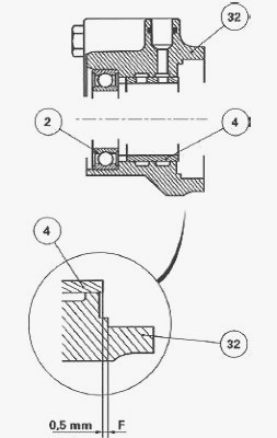
Check the bore of the ring (4) for correct surface condition. If the
diagnosis is inconclusive, replace the defective part(s). Check that the
seal rings (5) do not show any of the following: hardness; chipping;
cuts. Damage to the rings, even if it is minor, risks causing a leak
followed by a drop in pressure, which could disrupt the operation of the
clutch. If removed, using a press and a suitable fixture, Install and
position the ring (4) at a distance of 0.50 mm. This distance is
measured between mating face F of the bearing on the support (32) and
the end of the ring (4). Check that the hydraulic ports are not
obstructed.
Test Install the seal rings (5), new or reused, into the grooves of the
shaft of the clutch unit (9). Check that the seal rings turn freely in
their grooves. After this check: remove the seal rings and lightly smear
with miscible grease; definitively reinstall the seal rings; check that
the ends of the seal rings do not protrude beyond the rim of the shaft
of the clutch unit (9). Slide the support (32) onto the rear PTO clutch.
Install the circlip (1) on the shaft of the clutch unit (9). Check that
the circlip is correctly at the base of the groove.
Check that the PTO
clutch is not obstructed against its support (32) by ensuring there is a
slight clearance between the support and the clutch. Reinstall the
sealing ring (3) located at the end of the shaft of the clutch unit (9).
Check that the pins (P) are present. Install the clutch and its support
(32). Install and tighten screws V to 100-130 Nm. Reinstall: transfer
pipe and union used to lubricate the clutch; the 17-bar hydraulic pipe
(MF 6465, 6480) or 21-bar hydraulic pipe (MF 6485, 6490) located between
the clutch and the right-hand hydraulic cover plate.
Install the sensor(s) by proceeding as follows:
1) MF 6465, 6480 tractor with GTA1040 transmission - Lightly smear the
sensor thread (1) with Loctite FORM A Gasket 2 or equivalent. Tighten
home the sensor, without forcing, until its end is positioned against
the drive hub (21). Unscrew the sensor by three quarters of a turn.
Moderately tighten the nut.
2) MF 6485, 6490 tractor with GTA1540 transmission - Lightly smear the
sensor thread (1) with Loctite FORM A Gasket 2 or equivalent. Tighten
home the sensor, without forcing, until its end is positioned against
the drive hub (21). Unscrew the sensor by three quarters of a turn.
Moderately tighten the nut. Lightly smear the sensor thread (2) with
Loctite FORM A Gasket 2 or equivalent. Tighten home the sensor, without
forcing, until its end is positioned against the clutch unit (9).
Unscrew the sensor by three quarters of a turn. Moderately tighten the
nut.
Reinstall the right-hand hydraulic cover plate. Manually check the
backlash between the gear (28) and the hydraulic-pump-driven gears (Load
Sensing 110 l/min hydraulic equipment). Reconnect the tractor between
the gearbox and the rear axle. Start the engine. Check: operation of the
clutch and all hydraulic components; the tightness of the systems.
________________________________________________________________________________
________________________________________________________________________________
________________________________________________________________________________________
 SPECS
SPECS LOADERS
 MAINTENANCE
 PROBLEMS
________________________________________________________________________________________
________________________________________________________________________________________
| MF TRACTORS SPECIFICATIONS |
 130
130 133
133 145
145 155
155 158
158________________________________________________________________________________________
 165
165 175
175 185
185 188
188 230
230________________________________________________________________________________________
 254
254 254S
254S 284S
284S 294
294 353
353________________________________________________________________________________________
 290
290 362
362 375
375 390
390 398
398________________________________________________________________________________________
 399
399 590
590 690
690 1010
1010 1030
1030________________________________________________________________________________________
 1020
1020 1150
1150 2620
2620 2640
2640 2645
2645________________________________________________________________________________________
 1540
1540 1736
1736 2660
2660 3065
3065 3095
3095________________________________________________________________________________________
 3650
3650 3680
3680 4255
4255 4355
4355 4370
4370________________________________________________________________________________________
 3630
3630 3635
3635 4245
4245 4445
4445 4609
4609________________________________________________________________________________________
 4710
4710 5435
5435 5475
5475 5610
5610 5711
5711________________________________________________________________________________________
 6150
6150 6170
6170 6180
6180 6270
6270 6290
6290________________________________________________________________________________________
 6445
6445 6499
6499 6614
6614 6713
6713 7465
7465________________________________________________________________________________________
 7495
7495 7614
7614 7622
7622 7715
7715 7726
7726________________________________________________________________________________________
 8210
8210 8270
8270 8650
8650 8727
8727 GC1705
________________________________________________________________________________________
| MF FRONT END LOADERS |
 1464 Loader
 1466 Loader
 1040 Loader
 1070 Loader
 905 Loader
________________________________________________________________________________________
 906 Loader
 915 Loader
 916 Loader
 921 Loader
 926 Loader
________________________________________________________________________________________
 931 Loader
 933 Loader
 936 Loader
 938 Loader
 939 Loader
________________________________________________________________________________________
 940 Loader
 941 Loader
 945 Loader
 946 Loader
 948 Loader
________________________________________________________________________________________
 949 Loader
 950 Loader
 951 Loader
 955 Loader
 956 Loader
________________________________________________________________________________________
 958 Loader
 960 Loader
 961 Loader
 965 Loader
 966 Loader
________________________________________________________________________________________
 968 Loader
 975 Loader
 976 Loader
 978 Loader
 985 Loader
________________________________________________________________________________________
 FL.3114 X
 FL.3419 X
 FL.3522
 FL.3615
 FL.3619
________________________________________________________________________________________
 FL.3817
 FL.3819
 FL.3823
 FL.4018
 FL.4121
 916X Loader
 921X Loader
 926X Loader
 931X Loader
 936X Loader
________________________________________________________________________________________
 941X Loader
 946X Loader
 951X Loader
 956X Loader
 988 Loader
________________________________________________________________________________________
 FL.4125
 FL.4227
 FL.4124
 FL.4220
 FL.4323
________________________________________________________________________________________
 FL.4327
 FL.4621
 FL.4624
 FL.4628
 FL.5033
________________________________________________________________________________________
 DL95 Loader
 DL100 Loader
 DL120 Loader
 DL125 Loader
 DL130 Loader
________________________________________________________________________________________
 DL135 Loader
 DL250 Loader
 DL260 Loader
 L90 Loader
 L100 Loader
________________________________________________________________________________________
 L105E Loader
 L210 Loader
 1014 Loader
 1016 Loader
 1462 Loader
________________________________________________________________________________________
 1525 Loader
 1530 Loader
 232 Loader
 838 Loader
 848 Loader
________________________________________________________________________________________
 246 Loader
 1036 Loader
 1038 Loader
 1080 Loader
 856 Loader
________________________________________________________________________________________
| MF TRACTORS MAINTENANCE |
 1010
1010 1020
1020 1030
1030 1035
1035 1040
1040________________________________________________________________________________________
 1045
1045 1080
1080 1085
1085 1120
1120 1125
1125________________________________________________________________________________________
 1140
1140 1160
1160 1165
1165 1180
1180 1190
1190________________________________________________________________________________________
 1205
1205 1210
1210 1215
1215 1220
1220 1225
1225________________________________________________________________________________________
 1230
1230 1233
1233 1235
1235 1240
1240 1260
1260________________________________________________________________________________________
| MF TRACTORS TROUBLESHOOTING | ||||
| 1652 | 1749 | 2620 | 2725 | 2805 |
| 3050 | 3120 | 3640 | 3709 | 4245 |
| 4455 | 5320 | 5455 | 5613 | 6150 |
| 6280 | 6480 | 6615 | 7618 | 7720 |