
________________________________________________________________________________
Massey Ferguson 6465, 6480, 6485 - Rear PTO drive gears
540-1000 rpm PTO drive gears (2 speeds), 540E PTO drive gears (3
speeds)
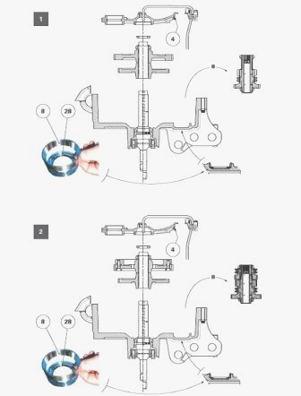
Disconnect the PTO housing from the centre housing. Position the PTO
housing horizontally, with the gears facing upwards. Remove the selector
rail(s). Remove the 540-1000 rpm or 540E driven gears (depending on
version) of the lower PTO shaftline. This removal must be carried out so
that unit B can then be removed. Take unit B out of the PTO housing
(shaft, driving gears, coupler(s) and tapered roller bearings). If
necessary, drive out the bearing cups (4) (8) and the oil deflector
(28), marking the direction in which they are fitted. Strip unit B by
carrying out the following: for the 540-1000 rpm PTO driving gears; for
the 540E PTO driving gears.
MF 6465, 6480, 6485, 6490 PTO - Remove the
drive gears
540-1000 rpm PTO driving gears
Remove the Vespel ring (30). Remove the bearing cone (7). Remove the
driving gear (11) and the coupler (5).
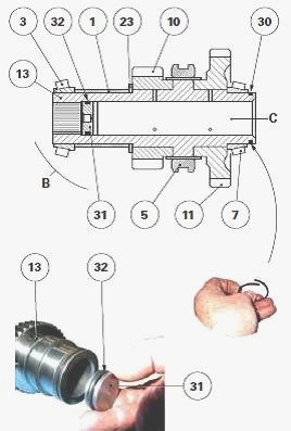
Extract the bearing cone (3). Remove the spacer (1), the washer with
flat section (23) and the driving gear (10). If necessary, drive out the
oil restrictor (31) from the shaft (13) and discard the "O" ring (32).
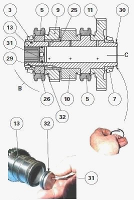
540E PTO driving gears
Remove the Vespel ring (30). Remove the bearing cone (7). Remove the
driving gear (11) and the coupler (5). Remove the bearing cone (3) and
the "O" ring (29). Remove the coupler (5) along with its hub (26).
Remove the driving gear (9), the shouldered ring (25) and the driving
gear (10). If necessary, drive out the oil restrictor (31) from the
shaft (13) and discard the "O" ring (32).
Check that the radial holes used to lubricate the gears and the
calibrated hole of the oil restrictor (31) are not blocked. Lubricate
the oil restrictor and the new "O" ring (32). Reassemble unit B by
carrying out the following: for the 540-1000 rpm PTO driving gears; for
the 540E PTO driving gears.
Massey Ferguson 6465, 6480, 6485, 6490 PTO -
Install the driving gears
540-1000 rpm PTO driving gears
On the shaft (13), install: oil restrictor (31) and a new "O" ring (32).
The oil restrictor (31) must be up against the shoulder of the shaft and
its calibrated hole facing towards oil chamber C; the gear (10); the
washer (23), with the larger surface positioned towards the gear; the
spacer (1). Using a press and a suitable fixture, Install the bearing
cone (3) against the spacer (1). Slide the following onto the other end
of the shaft (13): coupler (5); gear (11). Using a press and a suitable
fixture, Install the bearing cone (7) against the shoulder of the shaft.
Check that the coupler (5) slides freely towards the 540-1000 rpm gears.
Also check that these gears rotate freely.
540E PTO driving gears
On the shaft (13), Install: oil restrictor (31) and a new "O" ring (32).
The oil restrictor (31) must be up against the shoulder of the shaft and
its calibrated hole facing towards oil chamber C; gear (10); shouldered
ring (25); gear (9); hub (26); coupler (5) (540E); O-ring (29). The
O-ring (29) prevents loss of hydraulic flow and helps improves the
lubrication of the gear (9).
Reinstall the bearing cone (3). Slide the following onto the other end
of the shaft (13): coupler (5) (540 - 1000 rpm); gear (11). Using a
suitable fixture, Install the bearing cone (7) against the shoulder of
the shaft. Check that each coupler (5) slides freely towards its
respective gears (540-1000 rpm and 540E). Also check that these gears
rotate freely.
Driving gears for 540-1000 rpm or 540E PTO
Reinstall unit B into the PTO housing (shaft, driving gears, coupler(s)
and bearings). If the bearing cups (4) (8) and the deflector (28) were
driven out of their housing during disassembly, Install deflector by
positioning it. The oil deflector has a calibrated hole for lubricating
the bearings (7)(8); bearing cups (4) (8) against their respective
shoulders. Shim the bearings (3)(4) and (7)(8) of the layshaft (13).
Reinstall the 540-1000 rpm or 540E driven gears of the lower PTO
shaftline. Reinstall and adjust the selection mechanism. Reconnect the
PTO housing to the centre housing. Start the tractor engine and check
the rear PTO operation.
MF 6465, 6480, 6485, 6490 PTO - Shimming the
layshaft bearings
Preparing for shimming - For easier access to the driving gears and to
prevent inertia created by rotation of the driven gears, it is advisable
to carry out J1 shimming while temporarily excluding the following:
540-1000 rpm or 540E driven gears (depending on version) of the lower
PTO shaftline; selector rail(s) and fork(s); lower shaftline lubrication
pipe.
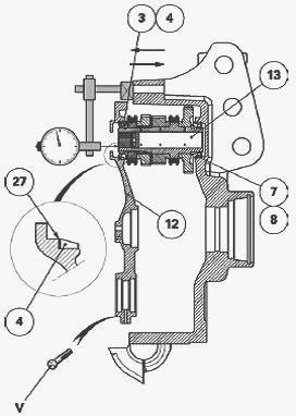
Lightly lubricate the bearing cones (3) (7) with clean transmission oil.
Check that the deflector (28) and the bearing cup (8) are present in the
PTO housing. Install the driving gears into the housing. Remove the
shim(s) (27) located in the bore of the bearing cup (4) of the removable
support (12). Reduce shim thickness by approx. 0.10 mm and reinstall
it/them in the place from which it was/they were removed. Install the
cup (4). Temporarily fix the removable support (12) to the PTO housing.
Tighten a few opposing V screws to 68-92 Nm.
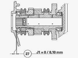
Shimming - Place a dial gauge feeler pin at the end of the shaft (13).
Push firmly on the driving gear assembly, turning it alternately to the
right and left to correctly Install the cones in their bearing cups. Set
the dial gauge to zero.
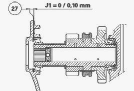
According to the temporary clearance reading on the dial gauge,
determine another shim (27) thickness to obtain a final clearance
depending on version): J1 = 0 to 0.10 mm. As far as possible, shim to
the minimum tolerance.
Massey Ferguson 6465, 6480, 6485, 6490 PTO -
Install and adjusting the cable controls
540-1000 rpm cable control
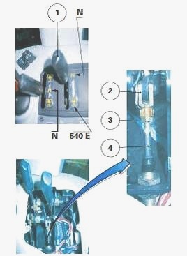
Install the cable at the cab end - Tighten the clevis (2) to the maximum
against the cable (4). Tighten the nut (3). Position the lever (1)
located on the console in neutral (N).
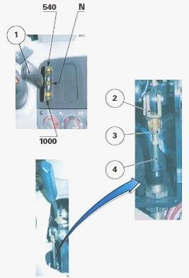
Install the cable to the lever. Tighten the sheath end on the support.
Position the feed-through conduit on the cab floor.
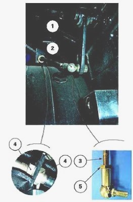
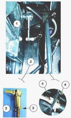
Installing the cable at the PTO housing end - Tighten the ball joint (2)
to the maximum against the cable (3). Tighten the nut (5). Position the
rod (1) (540-1000 rpm) located to the left of the PTO housing in neutral
(N). For easy access to the left-hand side of the PTO housing, position
the linkage arms in the raised position.
If the tractor is fitted with a 540E PTO power take-off, it is
recommended to place it in neutral before activating the 540-1000 rpm
power take-off. Slide the sheath end of the cable onto the support. If
possible, use nuts (4) to make the thread length identical on either
side of the support. Tighten the nuts. Fix the ball joint (2) on the
rod.
Checking the correct engagement of the 540-1000 rpm gears - Check that
gear engagement takes place normally in each lever position (540-1000
rpm and neutral) and that there is no sign of the cable being pinched.
If this is not the case, move the sheath end until the correct
adjustment is obtained.
540E cable control
The control lever (1) (540E) is located on the console, to the right of
the 540-1000 rpm lever. The 540E economy version follows the basic
concept of the 540-1000 rpm version and is completed by a set of
additional gears (driving and driven). The 540E control is mechanically
engaged by placing the 540-1000 rpm control in neutral first.
Installing the cable at the cab end - Tighten the clevis (2) to the
maximum against the cable (4). Tighten the nut (3). Position the lever
(1) located on the console in neutral (N). Install the cable to the
lever. Tighten the sheath stop on the support. Position the feed-through
conduit on the cab floor.
Installing the cable at the PTO housing end - Tighten the ball joint (2)
to the maximum against the cable (3). Tighten the nut (5). Position the
rod (540-1000 rpm) in neutral. Position the rod (1) (540E) located to
the right of the PTO housing in neutral. For easy access to the
right-hand side of the PTO housing, position the linkage arms in the
raised position.
Slide the sheath end of the cable onto the support. If possible, use
nuts (4) to make the thread length identical on either side of the
support. Tighten the nuts. Fix the ball joint (2) on the rod.
Checking the correct engagement of the 540E economy gear - Check that
gear engagement takes place normally in each lever position (540E and
neutral) and that there is no sign of the cable being pinched. If this
is not the case, move the sheath end until the correct adjustment is
obtained.
________________________________________________________________________________
________________________________________________________________________________
________________________________________________________________________________________
 SPECS
SPECS LOADERS
 MAINTENANCE
 PROBLEMS
________________________________________________________________________________________
________________________________________________________________________________________
| MF TRACTORS SPECIFICATIONS |
 130
130 133
133 145
145 155
155 158
158________________________________________________________________________________________
 165
165 175
175 185
185 188
188 230
230________________________________________________________________________________________
 254
254 254S
254S 284S
284S 294
294 353
353________________________________________________________________________________________
 290
290 362
362 375
375 390
390 398
398________________________________________________________________________________________
 399
399 590
590 690
690 1010
1010 1030
1030________________________________________________________________________________________
 1020
1020 1150
1150 2620
2620 2640
2640 2645
2645________________________________________________________________________________________
 1540
1540 1736
1736 2660
2660 3065
3065 3095
3095________________________________________________________________________________________
 3650
3650 3680
3680 4255
4255 4355
4355 4370
4370________________________________________________________________________________________
 3630
3630 3635
3635 4245
4245 4445
4445 4609
4609________________________________________________________________________________________
 4710
4710 5435
5435 5475
5475 5610
5610 5711
5711________________________________________________________________________________________
 6150
6150 6170
6170 6180
6180 6270
6270 6290
6290________________________________________________________________________________________
 6445
6445 6499
6499 6614
6614 6713
6713 7465
7465________________________________________________________________________________________
 7495
7495 7614
7614 7622
7622 7715
7715 7726
7726________________________________________________________________________________________
 8210
8210 8270
8270 8650
8650 8727
8727 GC1705
________________________________________________________________________________________
| MF FRONT END LOADERS |
 1464 Loader
 1466 Loader
 1040 Loader
 1070 Loader
 905 Loader
________________________________________________________________________________________
 906 Loader
 915 Loader
 916 Loader
 921 Loader
 926 Loader
________________________________________________________________________________________
 931 Loader
 933 Loader
 936 Loader
 938 Loader
 939 Loader
________________________________________________________________________________________
 940 Loader
 941 Loader
 945 Loader
 946 Loader
 948 Loader
________________________________________________________________________________________
 949 Loader
 950 Loader
 951 Loader
 955 Loader
 956 Loader
________________________________________________________________________________________
 958 Loader
 960 Loader
 961 Loader
 965 Loader
 966 Loader
________________________________________________________________________________________
 968 Loader
 975 Loader
 976 Loader
 978 Loader
 985 Loader
________________________________________________________________________________________
 FL.3114 X
 FL.3419 X
 FL.3522
 FL.3615
 FL.3619
________________________________________________________________________________________
 FL.3817
 FL.3819
 FL.3823
 FL.4018
 FL.4121
 916X Loader
 921X Loader
 926X Loader
 931X Loader
 936X Loader
________________________________________________________________________________________
 941X Loader
 946X Loader
 951X Loader
 956X Loader
 988 Loader
________________________________________________________________________________________
 FL.4125
 FL.4227
 FL.4124
 FL.4220
 FL.4323
________________________________________________________________________________________
 FL.4327
 FL.4621
 FL.4624
 FL.4628
 FL.5033
________________________________________________________________________________________
 DL95 Loader
 DL100 Loader
 DL120 Loader
 DL125 Loader
 DL130 Loader
________________________________________________________________________________________
 DL135 Loader
 DL250 Loader
 DL260 Loader
 L90 Loader
 L100 Loader
________________________________________________________________________________________
 L105E Loader
 L210 Loader
 1014 Loader
 1016 Loader
 1462 Loader
________________________________________________________________________________________
 1525 Loader
 1530 Loader
 232 Loader
 838 Loader
 848 Loader
________________________________________________________________________________________
 246 Loader
 1036 Loader
 1038 Loader
 1080 Loader
 856 Loader
________________________________________________________________________________________
| MF TRACTORS MAINTENANCE |
 1010
1010 1020
1020 1030
1030 1035
1035 1040
1040________________________________________________________________________________________
 1045
1045 1080
1080 1085
1085 1120
1120 1125
1125________________________________________________________________________________________
 1140
1140 1160
1160 1165
1165 1180
1180 1190
1190________________________________________________________________________________________
 1205
1205 1210
1210 1215
1215 1220
1220 1225
1225________________________________________________________________________________________
 1230
1230 1233
1233 1235
1235 1240
1240 1260
1260________________________________________________________________________________________
| MF TRACTORS TROUBLESHOOTING | ||||
| 1652 | 1749 | 2620 | 2725 | 2805 |
| 3050 | 3120 | 3640 | 3709 | 4245 |
| 4455 | 5320 | 5455 | 5613 | 6150 |
| 6280 | 6480 | 6615 | 7618 | 7720 |