
________________________________________________________________________________
Massey Ferguson 6465, 6480, 6490 Rear PTO - Intermediate shaft and driving gears
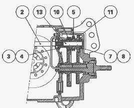
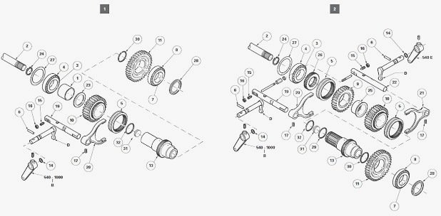
On MF 6465, 6480, 6485, 6490 tractors the upper shaftline of the rear
PTO comprises: PTO clutch (1); intermediate shaft (2); layshaft (13);
tapered roller bearings (3) (4) and (7) (8); driving gears (10) (11)
(540-1000 rpm PTO version) or driving gears (10) (11) and (9) (540 E PTO
(power take-off) version); a coupler (5) (540-1000 rpm power take-off
PTO version) or two couplers (5) (540 E PTO version).
Shims (27) fitted at the front end of the layshaft (13) allow the
clearance of the tapered roller bearings to be adjusted.
On the 540-1000 rpm PTO version, the 540-1000 rpm power take-off lever
installed on the left-hand side of the PTO housing (as viewed from the
operator's seat), activates a selector rail (19) and a coupler (5). The
coupler (5) moves either towards the 540-rpm gear (10) or towards the
1000-rpm gear (11) according to the required speed. On the 540E PTO
version, a second lever connected to its own coupler engages this
coupling with the gear (9) to obtain the 540 E economic speed. This
second lever is installed on the right-hand side of the rear PTO housing
(as viewed from the operator's seat). The 540-1000 rpm and 540E PTO rods
are each controlled from inside the cab by a cable.
Massey Ferguson 6465, 6480, 6490 - Rear PTO
Lubrication
The oil enters the rear PTO housing via a restrictor union. The flow
rate is then distributed via a restrictive hole (diameter approx. 1 mm)
to the driving gears and driven gears.
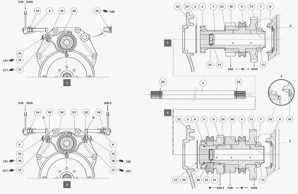
Parts list: (1) Spacer (540-1000 rpm PTO) (2)
Intermediate shaft (3) Bearing cone (4) Bearing cup (5) Coupler(s) (6)
Dowel(s) (7) Bearing cone (8) Bearing cup (9) 540 E driving gear (10)
540 rpm driving gear (11) 1000 rpm driving gear (12) Removable support
(13) Layshaft (14) "O" ring(s) (15) Pushrod screw (16) Nut (17) Set
screw (18) Cup plug (19) 540-1000 rpm selector rail (20) 540-1000 rpm
fork (21) 540 E fork (22) 540 E selector rail (23) Washer with flat
section (540-1000 rpm version) (24) Circlip(s) (25) Shouldered ring (540
E version) (26) 540 E hub (27) Shim(s) (28) Oil deflector (29) "O" ring
(540 E version) (30) Vespel ring (31) Oil restrictor (32) "O" ring, F -
Details 540-1000 rpm PTO (power take-off) / 540E PTO
Massey Ferguson 6465, 6480, 6490 - Partial
kinematics and operation of the safety lock
Partial kinematics
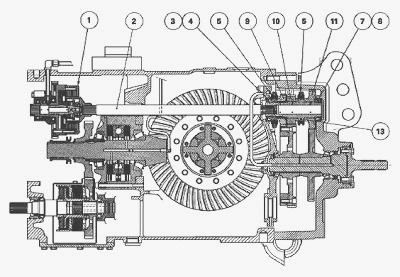
The engine speed is transmitted to the rear PTO clutch located at the
front of the centre housing via a shaftline which passes via: Power
Shuttle, the Dynashift and the GTA1040 transmission gearbox (MF 6465,
6480); Powershift, the Power Shuttle and the GTA1540 transmission
gearbox (MF 6485, 6490). The intermediate shaft (2) is splined to the
layshaft (13) and drives the driving gears (10) (11) and/or (9)
depending on the position of the coupler(s). When a gear transmits the
movement to the lower shaftline, the other gear(s) is/are passive and
turn(s) idle on its/their axis.
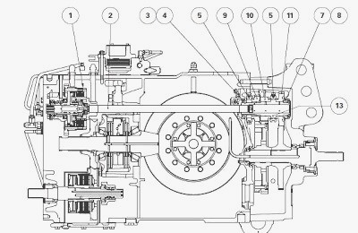
540E power take-off safety lock
The safety lock device is only fitted on the 3-speed PTO version
(540-1000 rpm and 540E). It is located at the top and within the rear
PTO housing. It acts as a lock due to the round end of its two
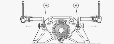
adjustable rails. The selector rails (19) and (22) for the forks are
machined in order to house the locks and to allow their movement.
Operation
When the selector rail (19) engages the 540-rpm gear, it forces the lock
(3) out of its housing. The lock (3) then pushes lock (2), which locks
the 540E selector rail (22) in neutral position and thus prevents any
movement. This principle can be applied to the 540E and 1000-rpm gears.
Massey Ferguson 6465, 6480, 6490 -
Disassembling, reassembling and adjusting the safety lock and adjusting
a pushrod screw
Disassembling the safety lock (540E PTO)
Disconnect the PTO housing from the centre housing. Using a locally
obtained M5 screw, extract the dowel (6) using the tapped hole T in the
dowel. Extract finger D from the selector rail (22) (540E PTO control)
by pulling the rod out of the housing. Remove the set screw (17) fixing
the fork (21) to the selector rail. Using the adjustable sleeve (1) (no
left or right-hand screw), shorten the length of the safety locks (2)
(3). Unscrew: nut (16); pushrod screw (15). Remove the selector rail
(22). Visually note the assembly. Separate and remove the safety locks
(2)(3).
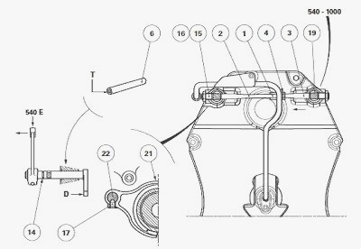
Reassembling the safety lock (540E PTO)
Reassemble the safety lock device by following steps reverse order.
During the reassembly process, observe the following points: Lightly
smear the thread of the set screw (17) with Loctite 221 or equivalent.
Tighten this screw to a torque of 25-35 Nm. If necessary, replace the
"O" ring (14) by sliding it over the pin of finger D via the outside of
the housing so as not to break it on the sharp edge of the housing. Do
not forget to refit the dowel (6). Adjust the safety lock and the
pushrod screw(s).
Adjusting the safety lock (540E power
take-off)
Place a selector rail in neutral position. Engage a gear using the other
selector rail. Adjust the sleeve (1) (no left or right-hand screw) to
give a slight clearance of approx. 0.1 mm. Tighten the nut. Activate
each gear alternately and several times. Engage a 540 or 1000-rpm gear.
Test the safety device by trying to engage the 540E gear: this gear
should not engage. Test the safety device for the other two gears in the
same way.
Adjusting a pushrod screw
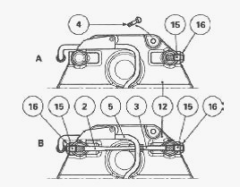
Position the selector rail concerned so that one of the flat sections is
opposite the tapped hole of the fork pushrod screw (15). Tighten the
pushrod screw without forcing it in order to compress the ball, then
loosen it by one quarter turn. Clean the thread of the pushrod screw
(15) and the nut (16). Lightly smear the thread of the nut (16) with
Loctite 242 or equivalent. Tighten this nut to 15-20 Nm while holding
the pushrod screw (15) in place. Check that the fork lock matches.
Reconnect the PTO housing to the centre housing. Start the tractor
engine and check the PTO operation.
Massey Ferguson 6465, 6480, 6490 - Removing
and install the selection mechanism
Disconnect the PTO housing from the centre housing. 540-1000 rpm PTO (A)
- Unscrew: nut (16); pushrod screw (15).
540E power take-off (B) - Unscrew: nut (16); pushrod screw (15). Shorten
the length of the safety locks (2) (3). 540-1000 rpm or 540E power
take-off - Remove the lubrication pipe (5). Remove the removable support
(12) holding the front end of the PTO shafts (upper and lower) in place.
Removal of the removable support (12) always involves removing the rear
bearing and the Ground speed PTO coupler (if fitted). Remove the
selector rail(s) (19) (22). Remove unit B, which amongst other
components, comprises the driving gears. Separate the fork(s) from the
coupler(s) (depending on version). Install the fork(s) on the coupler(s)
(depending on version). Reinstall unit B.
Check that the shims and tapered roller bearing cups are present in the
removable support (12). Reinstall the removable support (12) with the
safety locks (2)(3). Lightly smear the thread of the screws (4) with
Loctite 242 or equivalent. Tighten these screws to 68-92 Nm. Install the
lubrication pipe (5), replacing the "O" rings beforehand. Reinstall the
selector rail(s) and the pushrod screw(s) (depending on version). Carry
out adjustments. Reconnect the PTO housing to the centre housing. Start
the tractor engine and check the power take-off PTO operation.
________________________________________________________________________________
________________________________________________________________________________
________________________________________________________________________________________
 SPECS
SPECS LOADERS
 MAINTENANCE
 PROBLEMS
________________________________________________________________________________________
________________________________________________________________________________________
| MF TRACTORS SPECIFICATIONS |
 130
130 133
133 145
145 155
155 158
158________________________________________________________________________________________
 165
165 175
175 185
185 188
188 230
230________________________________________________________________________________________
 254
254 254S
254S 284S
284S 294
294 353
353________________________________________________________________________________________
 290
290 362
362 375
375 390
390 398
398________________________________________________________________________________________
 399
399 590
590 690
690 1010
1010 1030
1030________________________________________________________________________________________
 1020
1020 1150
1150 2620
2620 2640
2640 2645
2645________________________________________________________________________________________
 1540
1540 1736
1736 2660
2660 3065
3065 3095
3095________________________________________________________________________________________
 3650
3650 3680
3680 4255
4255 4355
4355 4370
4370________________________________________________________________________________________
 3630
3630 3635
3635 4245
4245 4445
4445 4609
4609________________________________________________________________________________________
 4710
4710 5435
5435 5475
5475 5610
5610 5711
5711________________________________________________________________________________________
 6150
6150 6170
6170 6180
6180 6270
6270 6290
6290________________________________________________________________________________________
 6445
6445 6499
6499 6614
6614 6713
6713 7465
7465________________________________________________________________________________________
 7495
7495 7614
7614 7622
7622 7715
7715 7726
7726________________________________________________________________________________________
 8210
8210 8270
8270 8650
8650 8727
8727 GC1705
________________________________________________________________________________________
| MF FRONT END LOADERS |
 1464 Loader
 1466 Loader
 1040 Loader
 1070 Loader
 905 Loader
________________________________________________________________________________________
 906 Loader
 915 Loader
 916 Loader
 921 Loader
 926 Loader
________________________________________________________________________________________
 931 Loader
 933 Loader
 936 Loader
 938 Loader
 939 Loader
________________________________________________________________________________________
 940 Loader
 941 Loader
 945 Loader
 946 Loader
 948 Loader
________________________________________________________________________________________
 949 Loader
 950 Loader
 951 Loader
 955 Loader
 956 Loader
________________________________________________________________________________________
 958 Loader
 960 Loader
 961 Loader
 965 Loader
 966 Loader
________________________________________________________________________________________
 968 Loader
 975 Loader
 976 Loader
 978 Loader
 985 Loader
________________________________________________________________________________________
 FL.3114 X
 FL.3419 X
 FL.3522
 FL.3615
 FL.3619
________________________________________________________________________________________
 FL.3817
 FL.3819
 FL.3823
 FL.4018
 FL.4121
 916X Loader
 921X Loader
 926X Loader
 931X Loader
 936X Loader
________________________________________________________________________________________
 941X Loader
 946X Loader
 951X Loader
 956X Loader
 988 Loader
________________________________________________________________________________________
 FL.4125
 FL.4227
 FL.4124
 FL.4220
 FL.4323
________________________________________________________________________________________
 FL.4327
 FL.4621
 FL.4624
 FL.4628
 FL.5033
________________________________________________________________________________________
 DL95 Loader
 DL100 Loader
 DL120 Loader
 DL125 Loader
 DL130 Loader
________________________________________________________________________________________
 DL135 Loader
 DL250 Loader
 DL260 Loader
 L90 Loader
 L100 Loader
________________________________________________________________________________________
 L105E Loader
 L210 Loader
 1014 Loader
 1016 Loader
 1462 Loader
________________________________________________________________________________________
 1525 Loader
 1530 Loader
 232 Loader
 838 Loader
 848 Loader
________________________________________________________________________________________
 246 Loader
 1036 Loader
 1038 Loader
 1080 Loader
 856 Loader
________________________________________________________________________________________
| MF TRACTORS MAINTENANCE |
 1010
1010 1020
1020 1030
1030 1035
1035 1040
1040________________________________________________________________________________________
 1045
1045 1080
1080 1085
1085 1120
1120 1125
1125________________________________________________________________________________________
 1140
1140 1160
1160 1165
1165 1180
1180 1190
1190________________________________________________________________________________________
 1205
1205 1210
1210 1215
1215 1220
1220 1225
1225________________________________________________________________________________________
 1230
1230 1233
1233 1235
1235 1240
1240 1260
1260________________________________________________________________________________________
| MF TRACTORS TROUBLESHOOTING | ||||
| 1652 | 1749 | 2620 | 2725 | 2805 |
| 3050 | 3120 | 3640 | 3709 | 4245 |
| 4455 | 5320 | 5455 | 5613 | 6150 |
| 6280 | 6480 | 6615 | 7618 | 7720 |