
________________________________________________________________________________
Massey Ferguson 6465, 6480, 6485 - Rear PTO output shaft and brake
On MF 6465, 6480, 6485, 6490 tractors equipped with GTA1040 or GTA1540
transmission, the rear PTO may be installed with a 540E economy version.
The economy version follows the principle of the 540-1000 rpm standard
equipment and is produced by fitting an additional 540E gear (10)
centred and fitted to the 540 rpm gear (7) via a screw (11). The profile
of the 1000 rpm driven gear differs according to the transmission type
and equipment installed.
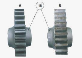
The profile of the 1000 rpm driving gear also differs according to the
transmission type and equipment fitted. Regardless of the type of PTO,
the driven gears are constantly meshed with the driving gears driven by
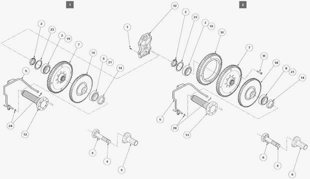
the upper shaftline. The output shaft (13) is fitted on tapered roller
bearings (3) (8) and (19) (21) mounted respectively in the rear PTO
housing and in the removable front support (12).
The 540-1000 rpm gears (7) (18) are splined to the output shaft and
clamped between the bearing cones by the nut (2). The rear bearing is
sealed by the seal (14). The preload of the tapered roller bearings is
adjusted by using the shims (23) inserted between the removable front
support (12) and the bearing cup (19). Sensor C (if fitted) located to
the right of the PTO housing informs the tractor's electronic system of
the speed of the output shaft via the 540 rpm driven gear. A threaded
plug C blocks the sensor port if the sensor is not fitted.
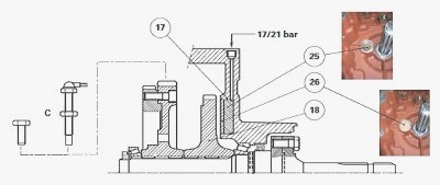
The rear PTO brake is a cylindrical piston (25) fitted with an "O" ring
(17). This piston is housed in a bore of the rear PTO housing. When the
PTO clutch supply is interrupted, the 17 or 21 bar pressure is applied
to the brake. The piston then travels towards the machined face of the
1000 rpm driven gear (18) and compresses this gear via a friction washer
(26) in order to gradually slow down the rotation of the mechanical
sections of the PTO until they are completely immobilised.
Massey Ferguson 6465, 6480, 6485, 6490 - PTO
Lubrication
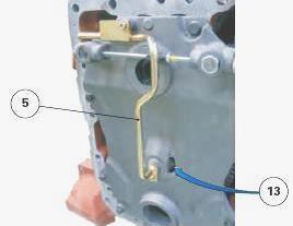
The lower shaftline of the PTO is lubricated by a pipe (5) which carries
transmission oil to the axial port and the radial holes in the output
shaft (13). The oil lubricates the splines on the 540-1000 rpm gears and
the rear bearing (8) (21). The front bearing (3) (19) is lubricated by
oil splashing from the gears as they move.
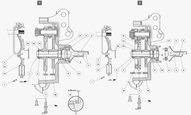
Parts list: (1) Screw (2) Undercut nut (3) Bearing cone
(4) Long or short flanged shaft (interchangeable shaft) (5) Lubrication
pipe (6) Screw (7) 540 rpm driven gear (8) Bearing cone (9) Guard (10)
540 E driven gear (11) Screw (12) Removable front support (13) Output
shaft (14) Seal (18) 1000 rpm driven gear (19) Bearing cup (21) Bearing
cup (23) Shims (24) "O" ring, A - Details 540-1000 rpm PTO/ 540E PTO
MF 6465, 6480, 6485, 6490 - Disassembling and
reassembling the 540-1000 PTO
Disconnect the PTO housing from the centre housing. All operations on
the PTO lower shaftline, including removal of the rear bearing gasket,
involves removing and install the PTO housing. Only the flanged shaft
(4) can be disassembled without having to carry out this removal
operation. Remove the sensor (if fitted) located to the right of the
rear housing of the PTO. Remove the 540-1000 rpm (2-speed) or 540E
(3-speed) PTO selection mechanism and the front removable support (12).
Disassembling the 540-1000 rpm driven gears
Immobilise the output shaft (13) by inserting a locally obtained M16
screw into hole T located between the rim of the output shaft and the
rear housing of the PTO. Unlock the nut (2) and loosen it using a
standard socket (55 mm flat). Extract the bearing cone (3). Remove the
540-1000 rpm driven gears (7) (18) from the rear housing of the PTO.
Using a soft hammer, tap the inside end of the output shaft and drive
the output shaft outwards. Recover the bearing cone (8). Drive out the
bearing cup (21). Drive out the seal (14) from the rear housing of the
PTO. Discard it.
Reassembling the 540-1000 rpm driven gears
Correctly position the new seal (14) in the rear housing of the PTO.
Using tool, gradually Install the new seal at a distance of 240 mm from
the face of the rear housing of the PTO. Install the bearing cup (21).
Lubricate the mating face of the seal (14) on the output shaft with
clean transmission oil. Engage the output shaft in the port on the rear
housing of the PTO. Install the bearing cone (8) on the output shaft
using a suitable locally obtained fitting drift. If necessary, shim the
tapered roller bearings (3) (19) and (8) (21).
Reinstall: driving gears;
540-1000 rpm driven gears (7) (18). Using a suitable fixture, Install
the bearing cone (3). Clean the threads of the new screw (2) and the
output shaft (13). Lightly smear the thread of the nut with Loctite 270
or equivalent. Screw this nut onto the output shaft. Immobilise the
output shaft. Definitively tighten the nut to 160-240 Nm. Using a
suitable punch, lock the nut in place by bending the collar into the
grooves of the output shaft without breaking it.
Massey Ferguson 6465, 6480, 6485, 6490 - Disassembly and reassembly the
540E PTO
Disassembling the 540E driven gears
Immobilise the output shaft (13) by inserting a locally obtained M16
screw into hole T located between the rim of the output shaft and the
rear housing of the PTO. Unlock the nut (2) and loosen it using a
standard socket (55 mm flat). Extract the bearing cone (3). Remove the
540E driven gears (7) (10) from the rear housing of the rear PTO. Turn
the 540E gear set over in order to access the screw heads (11). Then
slide the overturned 540E gear set onto the output shaft (13).
Immobilise the output shaft. Unscrew the screws (11). Remove the 540E
gear set from the rear housing of the PTO again and separate it. Using a
soft hammer, tap the inside end of the output shaft and drive the output
shaft outwards. Recover the bearing cone (8). Drive out the bearing cup
(21). Drive out the seal (14) from the rear housing of the PTO. Discard
it.
Reassembling the 540E driven gears
Correctly position the new seal (14) in the rear housing of the PTO.
Using tool, gradually Install the new seal at a distance of 240 mm from
the face of the rear housing of the PTO. Install the bearing cup (21).
Lubricate the mating face of the seal (14) on the output shaft with
clean transmission oil. Engage the output shaft in the port on the rear
housing of the PTO. Install the bearing cone (8) on the output shaft
using a suitable locally obtained fitting drift. Clean the tapped holes
on the gear (10) and the screw (11) threads. Reassemble the 540E gear
set (7) (10). Lightly smear the thread of the screws (11) with Loctite
270 or equivalent. Screw in and tighten these screws to 110-140 Nm.
If necessary, shim the tapered roller bearings (3) (19) and (8) (21).
Reinstall: driving gears; 540E driven gears. Using a suitable fixture,
fit the bearing cone (3). Clean the threads of the new screw (2) and the
output shaft (13). Lightly smear the thread of the nut with Loctite 270
or equivalent. Screw this nut onto the output shaft. Immobilise the
output shaft. Definitively tighten the nut to 160-240 Nm. Using a
suitable punch, lock the nut in place by bending the collar into the
grooves of the output shaft without breaking it.
Install the 540-1000 rpm (2-speed) or 540E (3-speed) PTO mechanism and
the front removable support (12). If necessary and depending on the
option, Install the sensor located to the right of the rear PTO housing.
During the refitting process: lightly smear the sensor thread with
Loctite Form A Gasket 2 or equivalent; tighten home the sensor, without
forcing, until its end is positioned against the gear (7), unscrew the
sensor by three quarters of a turn; moderately tighten the nut.
Reconnect the PTO housing to the centre housing. Start the tractor
engine and check the PTO operation.
MF 6465, 6480, 6485, 6490 PTO - Shimming the output shaft
540-1000 rpm PTO
540E PTO
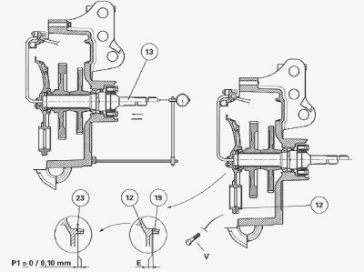
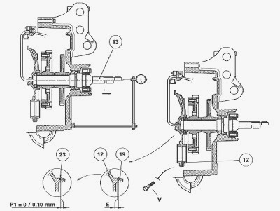
Preparation for shimming - Temporarily reassemble the lower PTO
shaftline in the rear housing with the output shaft (13), the lubricated
bearings and the driven gears. To reduce the inertia caused by the gears
during the alternating movement (right/left) from the output shaft
during the shimming operation, it is advisable to temporarily remove the
driving gears from the upper shaftline. Tighten the nut (2) to 160-240
Nm without Loctite. In space E of the removable front support (12),
slide a shim (23) thickness reduced from 0.15 to a maximum of 0.20 mm in
relation to the thickness found during disassembly. Install the bearing
cup (19). Temporarily fix the removable front support (12) to the rear
housing of the PTO. Tighten a few opposing V screws to 68-92 Nm.
Shimming
If necessary, to obtain a smooth area for the dial gauge feeler pin
contact, gently surface the rear end of the output shaft (13) using an
oilstone. Install the dial gauge feeler pin to the end of the output
shaft. Push firmly on the output shaft, turning it alternately to the
right and left in order to correctly fit the cones in the bearing cups.
Set the dial gauge to zero. According to the temporary clearance reading
measured on the dial gauge, determine another shim (23) thickness to
obtain a preload P1 = 0 to 0.10 mm. As far as possible, shim to the
maximum tolerance.
Massey Ferguson 6465, 6480, 6485, 6490 - Disassembling and reassembling
the rear PTO brake
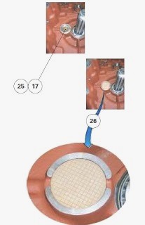
Remove the 540-1000 rpm or 540E driven gears (depending on version).
Remove the friction washer (26) (bi-metal). Using a jet of compressed
air, carefully drive out the brake piston (25) from the rear housing of
the PTO. Remove the "O" ring (27). Discard it. Clean the hydraulic
chamber of the brake piston (25). Check that there is no dirt inside the
17 or 21 bar channel. Install a new "O" ring (17) in the brake piston
(25) groove.
Install the brake piston fitted with its "O" ring in the rear housing of
the PTO, positioning its chamfered edge towards the hydraulic chamber.
The chamfer provides a correct hydraulic supply to the brake piston.
Refit the friction washer (26) (bi-metal) to the brake piston,
positioning its ribbed face towards the driven gear (18). The
lubrication between the brake piston and the friction washer is provided
by splashing caused by the moving parts. Reinstall the 540-1000 rpm or
540E driven gears (depending on version).
MF 6465, 6480, 6485, 6490 - Replacing the interchangeable shaft or
flanged shaft
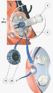
If it is necessary to remove and reinstall the interchangeable shaft
(4), proceed as follows. Immobilise the output shaft (13) by inserting a
locally obtained V M16 screw in hole T. Unscrew the screws (6). Remove
the interchangeable shaft (4). Check that the dowel (28) is present.
Install the interchangeable shaft. Screw in the screws. Tighten to a
torque of 120-140 Nm, immobilising the output shaft (13).
________________________________________________________________________________
________________________________________________________________________________
________________________________________________________________________________________
 SPECS
SPECS LOADERS
 MAINTENANCE
 PROBLEMS
________________________________________________________________________________________
________________________________________________________________________________________
| MF TRACTORS SPECIFICATIONS |
 130
130 133
133 145
145 155
155 158
158________________________________________________________________________________________
 165
165 175
175 185
185 188
188 230
230________________________________________________________________________________________
 254
254 254S
254S 284S
284S 294
294 353
353________________________________________________________________________________________
 290
290 362
362 375
375 390
390 398
398________________________________________________________________________________________
 399
399 590
590 690
690 1010
1010 1030
1030________________________________________________________________________________________
 1020
1020 1150
1150 2620
2620 2640
2640 2645
2645________________________________________________________________________________________
 1540
1540 1736
1736 2660
2660 3065
3065 3095
3095________________________________________________________________________________________
 3650
3650 3680
3680 4255
4255 4355
4355 4370
4370________________________________________________________________________________________
 3630
3630 3635
3635 4245
4245 4445
4445 4609
4609________________________________________________________________________________________
 4710
4710 5435
5435 5475
5475 5610
5610 5711
5711________________________________________________________________________________________
 6150
6150 6170
6170 6180
6180 6270
6270 6290
6290________________________________________________________________________________________
 6445
6445 6499
6499 6614
6614 6713
6713 7465
7465________________________________________________________________________________________
 7495
7495 7614
7614 7622
7622 7715
7715 7726
7726________________________________________________________________________________________
 8210
8210 8270
8270 8650
8650 8727
8727 GC1705
________________________________________________________________________________________
| MF FRONT END LOADERS |
 1464 Loader
 1466 Loader
 1040 Loader
 1070 Loader
 905 Loader
________________________________________________________________________________________
 906 Loader
 915 Loader
 916 Loader
 921 Loader
 926 Loader
________________________________________________________________________________________
 931 Loader
 933 Loader
 936 Loader
 938 Loader
 939 Loader
________________________________________________________________________________________
 940 Loader
 941 Loader
 945 Loader
 946 Loader
 948 Loader
________________________________________________________________________________________
 949 Loader
 950 Loader
 951 Loader
 955 Loader
 956 Loader
________________________________________________________________________________________
 958 Loader
 960 Loader
 961 Loader
 965 Loader
 966 Loader
________________________________________________________________________________________
 968 Loader
 975 Loader
 976 Loader
 978 Loader
 985 Loader
________________________________________________________________________________________
 FL.3114 X
 FL.3419 X
 FL.3522
 FL.3615
 FL.3619
________________________________________________________________________________________
 FL.3817
 FL.3819
 FL.3823
 FL.4018
 FL.4121
 916X Loader
 921X Loader
 926X Loader
 931X Loader
 936X Loader
________________________________________________________________________________________
 941X Loader
 946X Loader
 951X Loader
 956X Loader
 988 Loader
________________________________________________________________________________________
 FL.4125
 FL.4227
 FL.4124
 FL.4220
 FL.4323
________________________________________________________________________________________
 FL.4327
 FL.4621
 FL.4624
 FL.4628
 FL.5033
________________________________________________________________________________________
 DL95 Loader
 DL100 Loader
 DL120 Loader
 DL125 Loader
 DL130 Loader
________________________________________________________________________________________
 DL135 Loader
 DL250 Loader
 DL260 Loader
 L90 Loader
 L100 Loader
________________________________________________________________________________________
 L105E Loader
 L210 Loader
 1014 Loader
 1016 Loader
 1462 Loader
________________________________________________________________________________________
 1525 Loader
 1530 Loader
 232 Loader
 838 Loader
 848 Loader
________________________________________________________________________________________
 246 Loader
 1036 Loader
 1038 Loader
 1080 Loader
 856 Loader
________________________________________________________________________________________
| MF TRACTORS MAINTENANCE |
 1010
1010 1020
1020 1030
1030 1035
1035 1040
1040________________________________________________________________________________________
 1045
1045 1080
1080 1085
1085 1120
1120 1125
1125________________________________________________________________________________________
 1140
1140 1160
1160 1165
1165 1180
1180 1190
1190________________________________________________________________________________________
 1205
1205 1210
1210 1215
1215 1220
1220 1225
1225________________________________________________________________________________________
 1230
1230 1233
1233 1235
1235 1240
1240 1260
1260________________________________________________________________________________________
| MF TRACTORS TROUBLESHOOTING | ||||
| 1652 | 1749 | 2620 | 2725 | 2805 |
| 3050 | 3120 | 3640 | 3709 | 4245 |
| 4455 | 5320 | 5455 | 5613 | 6150 |
| 6280 | 6480 | 6615 | 7618 | 7720 |