
________________________________________________________________________________
Massey Ferguson 6497, 6499 - PTO clutch and brake
The multidisc clutch (15) is fitted in the PTO housing at the rear of the GPA30 transmission centre housing. It transmits engine speed to the driving pinions and combined driven pinions, via a proportional solenoid valve controlled by the tractor electronic system. The multidisc clutch consists of the following main components: 1) unit (6) supported by two bearings fitted in a unit/driving pinions assembly; 2) sleeve (10) force fitted into the unit (6).
This sleeve performs two functions: at the rear, it feeds the multidisc
clutch (17 bar low pressure) and lubricates the friction discs through
independent ports and channels; at the front, it supports the drive hub
(1) ball bearing (13). 3) two segments (22), which ensure the oil
tightness of the 17 bar low pressure circuit; 4) cover (32) fixed to the
clutch unit and enclosing: the friction discs splined to the hub (1),
the intermediate plates integral with the cover via catches.
MF 6497, 6499 - Power take-off clutch
Clutch engaged position
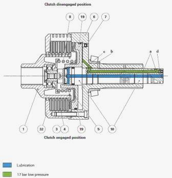
The clutch is fed by: 17 bar low pressure circuit; proportional solenoid
valve located on the right-hand hydraulic cover; external pipe going
from the right-hand hydraulic cover to the rear PTO housing.
The pressurised oil enters the sleeve (10) through channel A and flows
to hydraulic chamber B and channel C. The pressure pushes the
progressivity washer (5) and piston (19). The piston (19) compresses the
friction discs (4) splined to the hub (1) and the intermediate plates
(3) integral with the cover (32) via catches. The movement provided by
the layshafts is thus transmitted to the driving pinions via the unit
(6). Lubrication of the friction discs A channel D at the centre of the
sleeve (10) lubricates the friction discs in clutch engaged position.
Clutch disengaged position
When the solenoid valve no longer feeds the clutch, the piston (19) is
pressed against the housing (6) by the spring (8). The oil in the piston
(19) hydraulic chamber is directed to the return by the solenoid valve.
Simultaneously, the ball of valve (7) leaves its seat, thus assisting
the pressure release of the piston (19) hydraulic chamber.
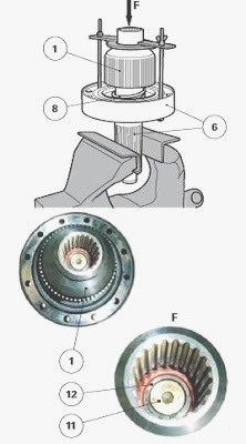
Massey Ferguson 6497, 6499 - PTO brake
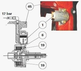
The cylinder of PTO brake piston (1) is located on the rear partition of
the centre housing (45). It is held in place by means of Mecanindus
pins. When the proportional solenoid valve feeds the PTO clutch, the
piston (19) is pressurised (clutch engaged position). The brake piston
(1) is at rest. The upper and lower PTO shaftlines can then rotate
freely. When the proportional solenoid valve no longer feeds the PTO
clutch, the piston (19) is at rest (declutched position).
The 17 bar low pressure is directed to the brake. It moves the piston
(1), which presses against the rim of the unit (6), thus braking the
upper and lower PTO shaftlines. Lubrication of the power take off brake
A restrictive channel at the centre of the piston (1) lubricates the rim
of the unit (6) when braking.
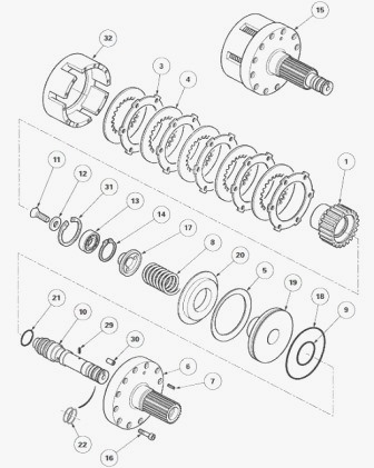
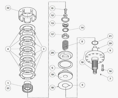
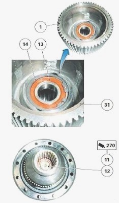
Parts list - (1) Drive hub (2) Bearing cone (3)
Intermediate plates (4) Friction discs (5) Progressivity washer (6)
Clutch housing (7) Valve (8) Spring (9) O’ring (10) Sleeve (11) Screw
(12) Chamfered washer (13) Ball bearing (14) Circlip (15) Clutch unit
assembly (16) Screw (17) Spring seat (18) O-ring (19) Piston (20)
Support (21) O’ring (22) Sealing rings (28) Secondary shaft (29)
Restrictor (30) Threaded plug (31) Oil deflector (32) Cover
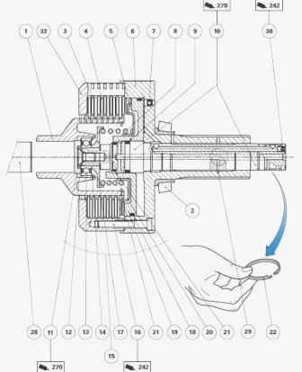
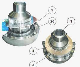
Parts list - (1) Drive hub (3) Intermediate plates (4)
Friction discs (5) Progressivity washer (6) Clutch housing (7) Valve (8)
Spring (9) O’ring (10) Sleeve (11) Screw (12) Chamfered washer (13) Ball
bearing (14) Circlip (15) Clutch unit assembly (16) Screw (17) Spring
seat (18) O-ring (19) Piston (20) Support (21) O-ring (22) Sealing rings
(29) Restrictor (30) Threaded plug (31) Oil deflector (32) Cover
MF 6497, 6499 - Disassembling and reassembling
the clutch unit assembly
Remove the block consisting of the clutch unit (15) and unit/driving
pinion(s) (23) assemblies. Split assemblies.
Disassembly
Tighten unit (6) in a vice fitted with soft jaw protectors. Loosen the
screws (16). Separate cover (32) from unit (6). Remove the friction
discs (4) and intermediate plates (3).
Using a locally made tool, hold the hub (1). Loosen the screw (11) and
remove the chamfered washer (12). Release the spring (8). Remove the
tool. Remove the drive hub (1), spring seat (17), spring (8), support
(20) and progressivity washer (5). If necessary, remove the circlip (14)
and extract the ball bearing (13).
Drive the piston (19) off the unit (6) using compressed air. Remove the
O'rings (9) (18) (21). If necessary, on the unit (6): extract the sleeve
(10); drive off the valve (7).
Reassembly
Clean and check all components. Replace any defective parts. If the
valve (7) had to be removed: Fit the valve on the unit (6). Check that
the valve is operating correctly by rapidly shaking the unit several
times: the movement of the ball in the valve must be heard.
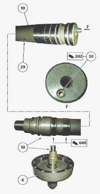
If the sleeve (10) had to be removed: Check that the restrictor (29) is
present on the sleeve. Lightly smear the sleeve with Loctite 648 or
equivalent. Fit it into the unit (6) using a press. Clean off any excess
Loctite. Using compressed air, check that the 17 bar low pressure
channel is not obstructed with Loctite. Lightly smear the plug (30)
thread with Loctite 242 or equivalent. Tighten this plug moderately.
Lubricate with clean transmission oil: new O-rings (9) (18) (21); rim of
the sleeve (10); piston (19).
Equip: the piston (19) with seal (18); the sleeve (10) with seals (9)
(21). Fit the piston into the unit (6) by gradually and alternately
striking around its top rim with a plastic mallet. Ensure there are no
seal fragments after fitting. Fit the bearing (13) into the drive hub
(1). Refit the circlip (14). If removed, refit the oil deflector (31) in
the drive hub.
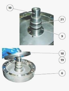
Refit: progressivity washer (5) according to the position indicated;
support (20); spring (8); spring seat (17); drive hub (1) with its
components. Compress the spring (8) using the tool. Refit the chamfered
washer (12), positioning its chamfer correctly. Lightly smear the thread
of the screw (11) with Loctite 270 or equivalent. Tighten this screw to
a torque of 24-28 Nm. Soak the friction discs (4) for a few minutes in a
clean transmission oil bath. Before assembly, ensure the oil has reached
all parts of the discs. Alternately fit on the drive hub (1), the
friction discs (4) and intermediate plates (3) removed during operation:
start by placing an intermediate plate (3) against the support (20).
Rotate the intermediate plates (3) to align the tabs T according to V.
Position the cover (32). Lightly smear the thread of the screws (16)
with Loctite 242 or equivalent. Tighten these screws to a torque of
25.5-34.5 Nm. Manually check that the drive hub (1) rotates freely in
the cover (32). Assemble and refit the block consisting of the clutch
unit (15) and unit/driving pinion(s) (23) assemblies.
________________________________________________________________________________
________________________________________________________________________________
________________________________________________________________________________________
 SPECS
SPECS LOADERS
 MAINTENANCE
 PROBLEMS
________________________________________________________________________________________
________________________________________________________________________________________
| MF TRACTORS SPECIFICATIONS |
 130
130 133
133 145
145 155
155 158
158________________________________________________________________________________________
 165
165 175
175 185
185 188
188 230
230________________________________________________________________________________________
 254
254 254S
254S 284S
284S 294
294 353
353________________________________________________________________________________________
 290
290 362
362 375
375 390
390 398
398________________________________________________________________________________________
 399
399 590
590 690
690 1010
1010 1030
1030________________________________________________________________________________________
 1020
1020 1150
1150 2620
2620 2640
2640 2645
2645________________________________________________________________________________________
 1540
1540 1736
1736 2660
2660 3065
3065 3095
3095________________________________________________________________________________________
 3650
3650 3680
3680 4255
4255 4355
4355 4370
4370________________________________________________________________________________________
 3630
3630 3635
3635 4245
4245 4445
4445 4609
4609________________________________________________________________________________________
 4710
4710 5435
5435 5475
5475 5610
5610 5711
5711________________________________________________________________________________________
 6150
6150 6170
6170 6180
6180 6270
6270 6290
6290________________________________________________________________________________________
 6445
6445 6499
6499 6614
6614 6713
6713 7465
7465________________________________________________________________________________________
 7495
7495 7614
7614 7622
7622 7715
7715 7726
7726________________________________________________________________________________________
 8210
8210 8270
8270 8650
8650 8727
8727 GC1705
________________________________________________________________________________________
| MF FRONT END LOADERS |
 1464 Loader
 1466 Loader
 1040 Loader
 1070 Loader
 905 Loader
________________________________________________________________________________________
 906 Loader
 915 Loader
 916 Loader
 921 Loader
 926 Loader
________________________________________________________________________________________
 931 Loader
 933 Loader
 936 Loader
 938 Loader
 939 Loader
________________________________________________________________________________________
 940 Loader
 941 Loader
 945 Loader
 946 Loader
 948 Loader
________________________________________________________________________________________
 949 Loader
 950 Loader
 951 Loader
 955 Loader
 956 Loader
________________________________________________________________________________________
 958 Loader
 960 Loader
 961 Loader
 965 Loader
 966 Loader
________________________________________________________________________________________
 968 Loader
 975 Loader
 976 Loader
 978 Loader
 985 Loader
________________________________________________________________________________________
 FL.3114 X
 FL.3419 X
 FL.3522
 FL.3615
 FL.3619
________________________________________________________________________________________
 FL.3817
 FL.3819
 FL.3823
 FL.4018
 FL.4121
 916X Loader
 921X Loader
 926X Loader
 931X Loader
 936X Loader
________________________________________________________________________________________
 941X Loader
 946X Loader
 951X Loader
 956X Loader
 988 Loader
________________________________________________________________________________________
 FL.4125
 FL.4227
 FL.4124
 FL.4220
 FL.4323
________________________________________________________________________________________
 FL.4327
 FL.4621
 FL.4624
 FL.4628
 FL.5033
________________________________________________________________________________________
 DL95 Loader
 DL100 Loader
 DL120 Loader
 DL125 Loader
 DL130 Loader
________________________________________________________________________________________
 DL135 Loader
 DL250 Loader
 DL260 Loader
 L90 Loader
 L100 Loader
________________________________________________________________________________________
 L105E Loader
 L210 Loader
 1014 Loader
 1016 Loader
 1462 Loader
________________________________________________________________________________________
 1525 Loader
 1530 Loader
 232 Loader
 838 Loader
 848 Loader
________________________________________________________________________________________
 246 Loader
 1036 Loader
 1038 Loader
 1080 Loader
 856 Loader
________________________________________________________________________________________
| MF TRACTORS MAINTENANCE |
 1010
1010 1020
1020 1030
1030 1035
1035 1040
1040________________________________________________________________________________________
 1045
1045 1080
1080 1085
1085 1120
1120 1125
1125________________________________________________________________________________________
 1140
1140 1160
1160 1165
1165 1180
1180 1190
1190________________________________________________________________________________________
 1205
1205 1210
1210 1215
1215 1220
1220 1225
1225________________________________________________________________________________________
 1230
1230 1233
1233 1235
1235 1240
1240 1260
1260________________________________________________________________________________________
| MF TRACTORS TROUBLESHOOTING | ||||
| 1652 | 1749 | 2620 | 2725 | 2805 |
| 3050 | 3120 | 3640 | 3709 | 4245 |
| 4455 | 5320 | 5455 | 5613 | 6150 |
| 6280 | 6480 | 6615 | 7618 | 7720 |