
________________________________________________________________________________
Massey Ferguson 6497, 6499 PTO - Flange shaft
MF 6497, 6499 - Removing and refitting the
flange shaft
The flange shaft may have 6, 20 or 21 splines.
Removal
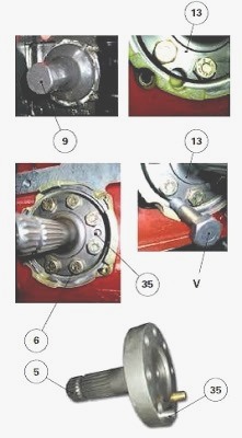
Remove off the protector (9). Immobilise the shiftable output shaft (13)
using a locally made V screw (M12). Loosen the screws (6). Remove the
flange shaft (5).
Refitting
Check for the presence of the locating pin (35). Refit the flange shaft.
Immobilise the output shaft. Tighten the screws (6) to a torque of
120-160 Nm. Manually check the mobility of the shiftable output shaft.
Refit the protector.
Massey Ferguson 6497, 6499 - Replacing the
rear bearing cassette seal
Split the rear PTO housing from the centre housing. Remove the rear
bearings and strip the shiftable output shaft (13). Note the position of
the cassette seal (14) in the rear bearing (22). Extract the cassette
seal. Discard the O'ring (15).
Replacing the seal
Clean and check all components. Replace any defective parts. Using the
tool, insert the cassette seal (14) in the bearing (22), turning the
seal lip towards the inside of the PTO housing.
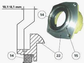
After fitting, check that the seal is positioned as indicated. Fit a new
O-ring (15) on the rear bearing (22). Lubricate the inner rim of the
cassette seal (14) and O-ring (15) with clean transmission oil.
Recondition and refit the bearing (22)/shiftable output shaft (13)
assembly on the PTO housing. Refit the driven pinions (18) (7). If
necessary, refit the sensor located on the lower right-hand side of the
power take-off housing. Moderately tighten the screw. Fit the PTO
housing in a vertical position. Assemble the rear PTO housing to the
centre housing.
Massey Ferguson 6497, 6499 - Shimming the rear
bearings
Split the rear PTO housing from the centre housing. Take off: 540/1000
rpm or, optionally, 750/1000 rpm driven pinions; rear bearing
(22)/shiftable output shaft (13) assembly; bearing cone (19) from the
PTO housing; flange shaft (5) of the shiftable output shaft (13). Note
dimensions A and B. To avoid being hindered by the resistance of the
cassette seal (14) on the shiftable output shaft (13), the seal should
be temporarily excluded during measurement of A and B values.
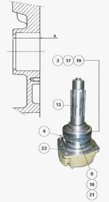
Dimension A - Using a depth gauge, measure dimension A on the PTO
housing. Dimension B - Rest the bearings/shiftable output shaft (13)
assembly on the rear bearing block. This assembly comprises: bearing
cones (3) (8) and their cup; castellated washer (4); circlips (16) (17).
Ask an operator to exert a strong and constant manual pressure on the
bearing cup (19).
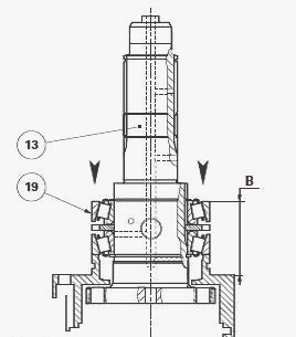
Simultaneously turn the shiftable output shaft (13) from left to right
so as to correctly "seat" the bearing cones in their cups. Measure
dimension B at two opposing points. Take the average of the two
measurements. Calculate B - A. Depending on the result, select a
thickness of shim(s) (23) to obtain a clearance J of 0.05 to 0.15 mm. If
possible, shim so as to obtain minimum tolerance.
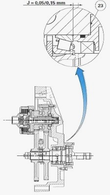
Refit: the flange shaft (5) on the shiftable output shaft; the bearing
cup (19) in the PTO housing; the rear bearing (22)/shiftable output
shaft (13) assembly fitted with: a new cassette seal (14), the shim(s)
(23) selected during operation. Lightly smear the thread of the screws
(2) with Loctite 242 or equivalent. Tighten these screws to a torque of
72-96 Nm. Refit the 540/1000 rpm or, optionally, 750/1000 rpm driven
pinions; Assemble the rear PTO housing to the centre housing.
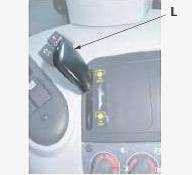
MF 6497, 6499 - Adjusting the cable control
On lever L - Push the control lever L located inside the cab to the 1000
rpm position.
Screw the clevis (1) flush with the threaded end of the cable (6). Fit
the clevis on the lever using clip (7). Tighten the nut (2). Position
the nut on the threaded sheath end (5). Fit the threaded sheath end on
the bracket. Tighten nut (4) and check that the cable is not constrained
in any way.
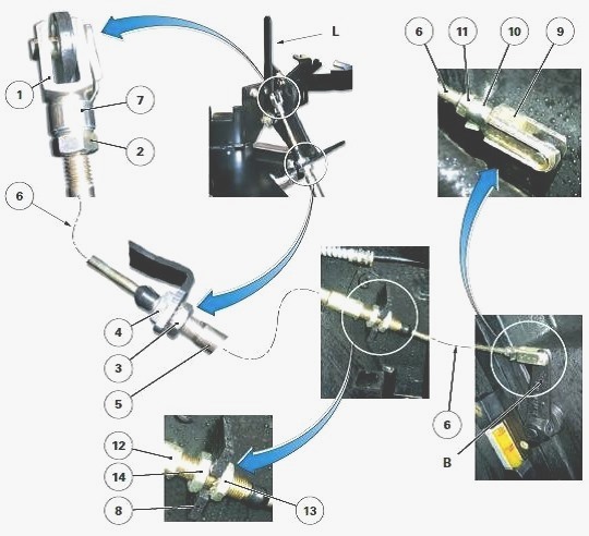
On link B - Turn link B towards the front of the tractor in the 1000 rpm
position. Screw clevis (9) flush with the threaded part of cable (6).
Fit clevis (9) on link B using clip (10). Tighten the nut (11). Adjust
the stop (12) on bracket (8) using nut (13), taking care that link B
does not move. Tighten nut (14) and check that the cable is not
constrained in any way. Check control operation in the 540 or 750 rpm
positions (depending on option) and in 1000 rpm position.
________________________________________________________________________________
________________________________________________________________________________
________________________________________________________________________________________
 SPECS
SPECS LOADERS
 MAINTENANCE
 PROBLEMS
________________________________________________________________________________________
________________________________________________________________________________________
| MF TRACTORS SPECIFICATIONS |
 130
130 133
133 145
145 155
155 158
158________________________________________________________________________________________
 165
165 175
175 185
185 188
188 230
230________________________________________________________________________________________
 254
254 254S
254S 284S
284S 294
294 353
353________________________________________________________________________________________
 290
290 362
362 375
375 390
390 398
398________________________________________________________________________________________
 399
399 590
590 690
690 1010
1010 1030
1030________________________________________________________________________________________
 1020
1020 1150
1150 2620
2620 2640
2640 2645
2645________________________________________________________________________________________
 1540
1540 1736
1736 2660
2660 3065
3065 3095
3095________________________________________________________________________________________
 3650
3650 3680
3680 4255
4255 4355
4355 4370
4370________________________________________________________________________________________
 3630
3630 3635
3635 4245
4245 4445
4445 4609
4609________________________________________________________________________________________
 4710
4710 5435
5435 5475
5475 5610
5610 5711
5711________________________________________________________________________________________
 6150
6150 6170
6170 6180
6180 6270
6270 6290
6290________________________________________________________________________________________
 6445
6445 6499
6499 6614
6614 6713
6713 7465
7465________________________________________________________________________________________
 7495
7495 7614
7614 7622
7622 7715
7715 7726
7726________________________________________________________________________________________
 8210
8210 8270
8270 8650
8650 8727
8727 GC1705
________________________________________________________________________________________
| MF FRONT END LOADERS |
 1464 Loader
 1466 Loader
 1040 Loader
 1070 Loader
 905 Loader
________________________________________________________________________________________
 906 Loader
 915 Loader
 916 Loader
 921 Loader
 926 Loader
________________________________________________________________________________________
 931 Loader
 933 Loader
 936 Loader
 938 Loader
 939 Loader
________________________________________________________________________________________
 940 Loader
 941 Loader
 945 Loader
 946 Loader
 948 Loader
________________________________________________________________________________________
 949 Loader
 950 Loader
 951 Loader
 955 Loader
 956 Loader
________________________________________________________________________________________
 958 Loader
 960 Loader
 961 Loader
 965 Loader
 966 Loader
________________________________________________________________________________________
 968 Loader
 975 Loader
 976 Loader
 978 Loader
 985 Loader
________________________________________________________________________________________
 FL.3114 X
 FL.3419 X
 FL.3522
 FL.3615
 FL.3619
________________________________________________________________________________________
 FL.3817
 FL.3819
 FL.3823
 FL.4018
 FL.4121
 916X Loader
 921X Loader
 926X Loader
 931X Loader
 936X Loader
________________________________________________________________________________________
 941X Loader
 946X Loader
 951X Loader
 956X Loader
 988 Loader
________________________________________________________________________________________
 FL.4125
 FL.4227
 FL.4124
 FL.4220
 FL.4323
________________________________________________________________________________________
 FL.4327
 FL.4621
 FL.4624
 FL.4628
 FL.5033
________________________________________________________________________________________
 DL95 Loader
 DL100 Loader
 DL120 Loader
 DL125 Loader
 DL130 Loader
________________________________________________________________________________________
 DL135 Loader
 DL250 Loader
 DL260 Loader
 L90 Loader
 L100 Loader
________________________________________________________________________________________
 L105E Loader
 L210 Loader
 1014 Loader
 1016 Loader
 1462 Loader
________________________________________________________________________________________
 1525 Loader
 1530 Loader
 232 Loader
 838 Loader
 848 Loader
________________________________________________________________________________________
 246 Loader
 1036 Loader
 1038 Loader
 1080 Loader
 856 Loader
________________________________________________________________________________________
| MF TRACTORS MAINTENANCE |
 1010
1010 1020
1020 1030
1030 1035
1035 1040
1040________________________________________________________________________________________
 1045
1045 1080
1080 1085
1085 1120
1120 1125
1125________________________________________________________________________________________
 1140
1140 1160
1160 1165
1165 1180
1180 1190
1190________________________________________________________________________________________
 1205
1205 1210
1210 1215
1215 1220
1220 1225
1225________________________________________________________________________________________
 1230
1230 1233
1233 1235
1235 1240
1240 1260
1260________________________________________________________________________________________
| MF TRACTORS TROUBLESHOOTING | ||||
| 1652 | 1749 | 2620 | 2725 | 2805 |
| 3050 | 3120 | 3640 | 3709 | 4245 |
| 4455 | 5320 | 5455 | 5613 | 6150 |
| 6280 | 6480 | 6615 | 7618 | 7720 |