
________________________________________________________________________________
Massey Ferguson 6497, 6499 PTO - Interchangeable output shaft
The GPA30 rear axle PTO housing encloses: driving pinions; driven
pinions (7) (18) (540/1000 rpm or, optionally, 750/1000 rpm);
interchangeable output shaft (13) of the lower shaftline. The
interchangeable output shaft is supported: 1) at the front by a
cylindrical roller bearing (24). This bearing is fitted into the front
bearing (1), which is attached to the rear partition of the centre
housing; 2) at the rear by a splined sleeve (5) which rotates on two
taper roller bearings (3) (19) and (8) (21).
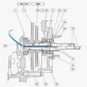
Taper roller bearing clearance is adjusted using shim(s) (23) placed
between the PTO housing and the rear bearing (22). The driven pinions
(7) (18) are constantly meshed with the upper shaftline driving pinions.
In the 540 rpm or 750 rpm configurations, the interchangeable output
shaft (13) is splined in rotation to the driven pinion (7). Pinion (18)
runs idle on the hub of the pinion (7) and the front end of the sleeve
(5). In the 1000 rpm configuration, the interchangeable output shaft
(13) is splined in rotation to the pinion (18). Pinion (7) then runs
idle in the bore of the pinion (18) and the front bearing (1). Friction
washers (10) (20) ensure the contact between rotating parts.

Castellated washer (4) is integral via a tab with sleeve (5) which
itself is splined to interchangeable output shaft (13). This washer
informs the tractor electronic system of the output speed of the
interchangeable shaft via a sensor (if fitted) located on the lower
right-hand side of the PTO housing.
Lubrication
A central channel with radial ports on the interchangeable output shaft
(13) provides splash lubrication of: driven pinions (7) (18); front
cylindrical roller bearing (24); friction washers (10) (20); rear taper
roller bearings (3) (19) and (8) (21). The oil tightness of the rear
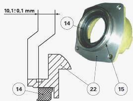
bearing is provided by cassette seal (14) and O'ring (15).
Parts list - (1) Front bearing (2) Screw (3) Bearing
cone (4) Castellated washer for sensor (if fitted) (5) Splined sleeve
(6) Snap ring (7) 540 or 750 rpm driven pinion (8) Bearing cone (9)
Protector (10) Friction washers (11) Screw (12) O’ring (13)
Interchangeable output shaft (14) Cassette seal (15) O’ring (16) Circlip
(17) Circlip (18) 1000 rpm driven pinion (19) Bearing cup (20) Friction
washer (21) Bearing cup (22) Rear bearing (23) Shim(s) (24) Cylindrical
roller bearing
Massey Ferguson 6497, 6499 - Removing and
refitting the 540/1000 rpm or 750/1000 rpm driven pinions
Split the rear PTO housing from the centre housing.
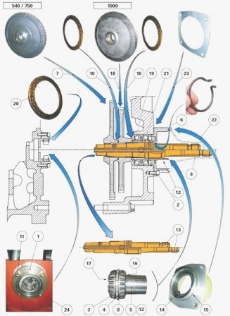
Removing the 540/1000 rpm driven pinions
Place the PTO housing flat on a workbench in order to allow removal of
the interchangeable output shaft (13). Recover the friction washer (20)
that may still be on the driven pinion (7). Take off: snap ring (6);
interchangeable output shaft (13); the driven pinion (7). Recover the
friction washer (10) fitted between the driven pinions (7) (18). Remove
the driven pinion (18). Recover the friction washer (10) fitted between
the pinion (18) and splined sleeve (5). Discard the O-ring (12).
Removing the 750/1000 rpm driven pinions
On the PTO with interchangeable output shaft (13), the removing
procedure for 750/1000 rpm driven pinions (7) (18) is similar to that
applied for the 540/1000 rpm driven pinions (7) (18).
MF 6497, 6499 - Refitting the 540/1000 rpm
driven pinions
Clean and check all components. Replace any defective parts. Check that:
the central channel and radial ports of the interchangeable output shaft
(13) are not obstructed; the splined sleeve (5) free from chippings
and/or burr. Grease the O’ring (12) with clean transmission oil. Refit
in the groove of the splined sleeve. Lightly smear a friction washer
(10) with miscible grease. Place the washer on the splined sleeve (5).
Stack the driven pinions (18) (7) on the splined sleeve (5), inserting
the second friction washer (10), previously smeared with miscible
grease, between each pinion. Grease the interchangeable output shaft
(13) with clean transmission oil. Engage it in the bores of the driven
pinions (18) (7) and push home against the shoulder of the splined
sleeve (5). Refit the snap ring (6). Lightly smear the friction washer
(20) with miscible grease. Place this washer against the cylindrical
roller bearing (24). Fit the PTO housing in a vertical position.
Refitting the 750/1000 rpm driven pinions
On the PTO with interchangeable output shaft (13), the refitting of
750/1000 rpm driven pinions (7) (18) is similar to that of the 540/1000
rpm driven pinions (7) (18). Assemble the rear PTO housing to the centre
housing.
Removing and refitting the front bearing
Split the rear PTO housing from the centre housing.
Removal - Recover the friction washer (20). If necessary, release screws
(11). Remove the front bearing block (1). Note the orientation of the
cylindrical roller bearing (24) in the front bearing block. Extract this
bearing.
Refitting - Clean and check all components. Replace any defective parts.
Using a suitable locally made fitting drift, fit the cylindrical roller
bearing into the bearing block, turning the rounded profile of its
metallic cage towards the interchangeable output shaft (13). Refit the
front bearing block (if removed). Lightly smear the thread of the screws
(11) with Loctite 242 or equivalent. Tighten these screws to a torque of
27-35 Nm. Lightly smear the friction washer (20) with miscible grease.
Place this washer against the cylindrical roller bearing (24). Assemble
the rear PTO housing to the centre housing.
Removing and refitting the rear bearings
Split the rear PTO housing from the centre housing.
Removal - Place the PTO housing flat on a workbench in order to allow
removal of the interchangeable output shaft (13). If fitted, remove the
sensor located on the lower right-hand side of the power take-off
housing. Remove: interchangeable output shaft (13); driven pinions (7)
(18). Loosen the screws (2). Remove the rear bearing assembly (22) which
consists of: cassette seal (14); O-ring (15); shim(s) (23). Remove the
cup (21) from the rear PTO housing. Remove the rear bearing assembly (5)
which consists of: bearing cones (3) (8); castellated washer (4);
circlips (16) (17). Remove cup (19).
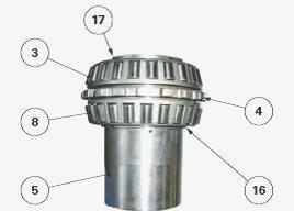
Remove the circlips (16) (17) from the splined sleeve (5). Split from
the splined sleeve (5): bearing cones (3) (8); castellated washer (4).
Refitting - Clean and check all components. Replace any defective parts.
Check that: central channel and radial ports of the interchangeable
output shaft (13) are not obstructed; splined sleeve (5) free from
chippings and/or burr. Refit on the splined sleeve (5): castellated
washer (4) by sliding its tab into the sleeve groove; bearing cones (3)
(8) on either side of the castellated washer; circlips (16) (17). Refit
on the PTO housing: bearing cup (19); rebuilt splined sleeve assembly
(5); bearing cup (21). If necessary, replace: cassette seal (14); O-ring
(15) of the rear bearing. Refit the original shim(s) (23) onto the
bearing block (22) only if the rear bearings do not need shimming.
The rear bearings must be shimmed if at least one of the following parts
needs replacing: PTO housing; castellated washer (4); bearing cones and
cups (3) (8) and (19) (21); rear bearing (22). Lubricate the cassette
seal (14) and O-ring (15). Refit the rear bearing (22) on the PTO
housing. Lightly smear the thread of the screws (2) with Loctite 242 or
equivalent. Tighten these screws to a torque of 72-96 Nm. Refit: the
driven pinions (18) (7); the interchangeable output shaft (13). If
necessary, refit the sensor located on the lower right-hand side of the
power take-off housing. Moderately tighten the screw. Fit the PTO
housing in a vertical position. Assemble the rear PTO housing to the
centre housing.
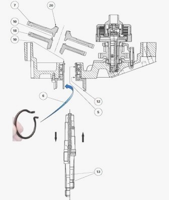
Massey Ferguson 6497, 6499 - Removing and
refitting the interchangeable output shaft
To avoid oil spillage when removing the interchangeable output shaft
(13): either partially drain the rear axle; or chock the tractor front
wheels using safety shims and raise the rear axle.
Removal
Take off: snap ring (6); interchangeable output shaft (13). If
necessary, discard the O'ring (12).
Refitting
Check that the splined sleeve (5) is free from chippings and/or burr. If
necessary, lubricate a new O’ring (12). Refit the seal in its groove.
Check that the central channel and radial ports of the interchangeable
output shaft (13) are not obstructed; Insert the interchangeable output
shaft into the splined sleeve (5). Turn the shaft right and left to
ensure that its splines mesh with those of the concerned driven pinion.
Refit snap ring (6). Depending on what was performed during operation:
either top up the oil levels in the housings and check the transparent
tube on the left-hand side of the centre housing; or place the tractor
rear wheels back on the ground and remove the trolley jack and safety
shims.
MF 6497, 6499 - Replacing the rear bearing
cassette seal
Partially drain the rear axle.
Extracting the seal
Loosen the screws (2). Remove the rear bearing (22) by pushing the
interchangeable output shaft forwards to hold the splined sleeve (5) in
place. Recover the shim(s) (23). Discard the O'ring (12). Note the
position of the cassette seal (14) in the rear bearing (22). Extract the
cassette seal. Discard the O'ring (15).
Replacing the seal
Clean and check all components. Replace any defective parts. Using the
tool, insert the cassette seal (14) in the bearing (22), turning the
seal lip towards the inside of the PTO housing. After inserting, check
that the seal is positioned as indicated in figure. Check that the
splined sleeve (5) and interchangeable output shaft (13) are correctly
positioned in the PTO housing.
Fit a new O’ring (15) on the rear bearing (22). Lubricate the inner rim
of the cassette seal (14) and O’ring (15) with clean transmission oil.
To facilitate refitting the rear bearing (22) on the PTO housing, screw
two opposing threaded rods (M10 x 50 mm approximately) into the tapped
screw holes (2). These rods shall be used as guides. Position the rear
bearing (22) with its original shim(s) on the threaded rods. Hold the
interchangeable output shaft pushed forwards.
Simultaneously screw two nuts (M10) with flat washers on the threaded
rods to uniformly insert: rear bearing (22) into the PTO housing;
cassette seal (14) on the sleeve (5). As soon as the rear bearing (22)
rests against the shim(s) (23), remove the nuts and threaded rods.
Lightly smear the thread of the screws (2) with Loctite 242 or
equivalent. Tighten these screws to a torque of 72-96 Nm. Top up the oil
level in the housings. Check it using the sight glass located to the
left of the centre housing.
Massey Ferguson 6497, 6499 - Shimming the rear
bearings
Split the rear PTO housing from the centre housing. Take off: 540/1000
rpm or, optionally, 750/1000 rpm driven pinions; sleeve assembly (5)
consisting of the bearing cones (3) (8) and their cups, of the splined
washer (4) and circlips (16) (17). Note dimensions A and B. To avoid
being hindered by the resistance of the cassette seal (14) on the
splined sleeve (5), the seal should be temporarily excluded during
measurement of A and B values.
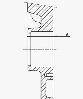
Dimension A - Using a depth gauge, measure dimension A on the PTO
housing. Dimension B - Place the sleeve assembly (5) consisting of the
bearing cones (3) (8) and their cups, of the splined washer (4) and
circlips (16) (17) against the rear bearing (22).
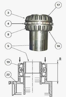
Ask an operator to exert a strong and constant manual pressure on the
bearing cup (19). Turn the splined sleeve (5) from left to right so as
to correctly seat the bearing cones in their cup. Measure dimension B at
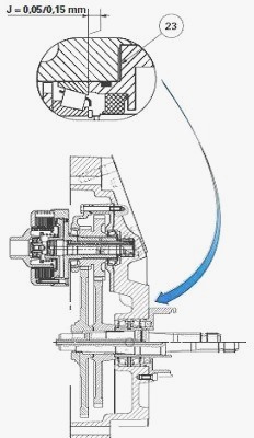
two opposing points. Take the average of the two measurements. Calculate
B - A. Depending on the result, select a thickness of shim(s) (23) to
obtain a clearance J of 0.05 to 0.15 mm. If possible, shim so as to
obtain minimum tolerance.
Refit: the sleeve assembly (5) consisting of the bearing cones (3) (8)
and their cup, of the splined washer (4) and circlips (16) (17); the
rear bearing (22), fitted with: a new cassette seal (14), the shim(s)
(23) selected during operation. Lightly smear the thread of the screws
(2) with Loctite 242 or equivalent. Tighten these screws to a torque of
72-96 Nm. Refit the 540/1000 rpm or, optionally, 750/1000 rpm driven
pinions; Assemble the rear PTO housing to the centre housing.
________________________________________________________________________________
________________________________________________________________________________
________________________________________________________________________________________
 SPECS
SPECS LOADERS
 MAINTENANCE
 PROBLEMS
________________________________________________________________________________________
________________________________________________________________________________________
| MF TRACTORS SPECIFICATIONS |
 130
130 133
133 145
145 155
155 158
158________________________________________________________________________________________
 165
165 175
175 185
185 188
188 230
230________________________________________________________________________________________
 254
254 254S
254S 284S
284S 294
294 353
353________________________________________________________________________________________
 290
290 362
362 375
375 390
390 398
398________________________________________________________________________________________
 399
399 590
590 690
690 1010
1010 1030
1030________________________________________________________________________________________
 1020
1020 1150
1150 2620
2620 2640
2640 2645
2645________________________________________________________________________________________
 1540
1540 1736
1736 2660
2660 3065
3065 3095
3095________________________________________________________________________________________
 3650
3650 3680
3680 4255
4255 4355
4355 4370
4370________________________________________________________________________________________
 3630
3630 3635
3635 4245
4245 4445
4445 4609
4609________________________________________________________________________________________
 4710
4710 5435
5435 5475
5475 5610
5610 5711
5711________________________________________________________________________________________
 6150
6150 6170
6170 6180
6180 6270
6270 6290
6290________________________________________________________________________________________
 6445
6445 6499
6499 6614
6614 6713
6713 7465
7465________________________________________________________________________________________
 7495
7495 7614
7614 7622
7622 7715
7715 7726
7726________________________________________________________________________________________
 8210
8210 8270
8270 8650
8650 8727
8727 GC1705
________________________________________________________________________________________
| MF FRONT END LOADERS |
 1464 Loader
 1466 Loader
 1040 Loader
 1070 Loader
 905 Loader
________________________________________________________________________________________
 906 Loader
 915 Loader
 916 Loader
 921 Loader
 926 Loader
________________________________________________________________________________________
 931 Loader
 933 Loader
 936 Loader
 938 Loader
 939 Loader
________________________________________________________________________________________
 940 Loader
 941 Loader
 945 Loader
 946 Loader
 948 Loader
________________________________________________________________________________________
 949 Loader
 950 Loader
 951 Loader
 955 Loader
 956 Loader
________________________________________________________________________________________
 958 Loader
 960 Loader
 961 Loader
 965 Loader
 966 Loader
________________________________________________________________________________________
 968 Loader
 975 Loader
 976 Loader
 978 Loader
 985 Loader
________________________________________________________________________________________
 FL.3114 X
 FL.3419 X
 FL.3522
 FL.3615
 FL.3619
________________________________________________________________________________________
 FL.3817
 FL.3819
 FL.3823
 FL.4018
 FL.4121
 916X Loader
 921X Loader
 926X Loader
 931X Loader
 936X Loader
________________________________________________________________________________________
 941X Loader
 946X Loader
 951X Loader
 956X Loader
 988 Loader
________________________________________________________________________________________
 FL.4125
 FL.4227
 FL.4124
 FL.4220
 FL.4323
________________________________________________________________________________________
 FL.4327
 FL.4621
 FL.4624
 FL.4628
 FL.5033
________________________________________________________________________________________
 DL95 Loader
 DL100 Loader
 DL120 Loader
 DL125 Loader
 DL130 Loader
________________________________________________________________________________________
 DL135 Loader
 DL250 Loader
 DL260 Loader
 L90 Loader
 L100 Loader
________________________________________________________________________________________
 L105E Loader
 L210 Loader
 1014 Loader
 1016 Loader
 1462 Loader
________________________________________________________________________________________
 1525 Loader
 1530 Loader
 232 Loader
 838 Loader
 848 Loader
________________________________________________________________________________________
 246 Loader
 1036 Loader
 1038 Loader
 1080 Loader
 856 Loader
________________________________________________________________________________________
| MF TRACTORS MAINTENANCE |
 1010
1010 1020
1020 1030
1030 1035
1035 1040
1040________________________________________________________________________________________
 1045
1045 1080
1080 1085
1085 1120
1120 1125
1125________________________________________________________________________________________
 1140
1140 1160
1160 1165
1165 1180
1180 1190
1190________________________________________________________________________________________
 1205
1205 1210
1210 1215
1215 1220
1220 1225
1225________________________________________________________________________________________
 1230
1230 1233
1233 1235
1235 1240
1240 1260
1260________________________________________________________________________________________
| MF TRACTORS TROUBLESHOOTING | ||||
| 1652 | 1749 | 2620 | 2725 | 2805 |
| 3050 | 3120 | 3640 | 3709 | 4245 |
| 4455 | 5320 | 5455 | 5613 | 6150 |
| 6280 | 6480 | 6615 | 7618 | 7720 |