
________________________________________________________________________________
Massey Ferguson 6497, 6499 PTO - Intermediate shafts
The upper shaftline of the GPA30 transmission rear PTO transmits engine
speed to the driving pinions through: multidisc clutch and series of
three shafts. Series of three shafts: mainshaft (19) splined to the
vibration damper, itself screwed to the engine flywheel; primary shaft
(14) splined to the mainshaft and in front of the hydraulic pump (Load
Sensing) drive pinion; secondary shaft (28) is splined at the front on
the hydraulic pump drive pinion and at the rear on the multidisc power
take-off clutch.
Description and layout of the rear PTO driving
pinions
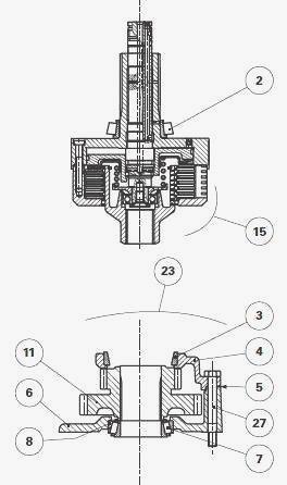
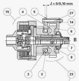
MF 6497, 6499 - Driving pinions for 2 speed
PTO with interchangeable output shaft
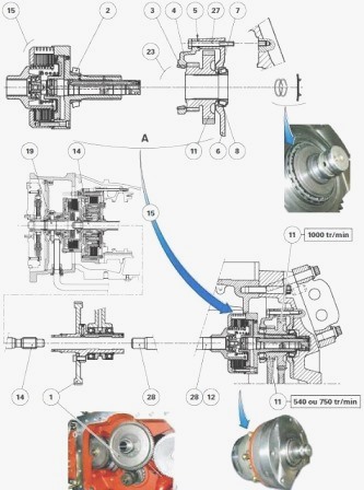
Parts list - (1) Hydraulic pump drive pinions (Load
Sensing) (2) Bearing cone (3) Bearing cup (4) Cover (5) Shim(s) (6) Unit
(7) Bearing cone (8) Bearing cup (11) Double driving pinion (12) Circlip
(14) Primary shaft (15) Clutch unit assembly (19) Mainshaft (23)
Unit/driving pinions assembly (27) Screw (28) Secondary shaft
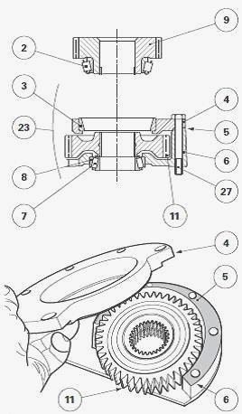
Driving pinions for 2 speed PTO with jaw
coupler on output shaft
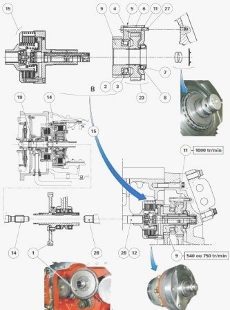
Parts list - (1) Hydraulic pump drive pinions (Load
Sensing) (2) Bearing cone (3) Bearing cup (4) Cover (5) Shim(s) (6) Unit
(7) Bearing cone (8) Bearing cup (9) 540 or 750 rpm driving pinion (11)
1000 rpm driving pinion (12) Circlip (14) Primary shaft (15) Clutch unit
assembly (19) Mainshaft (23) Unit/driving pinions assembly (27) Screw
(28) Secondary shaft
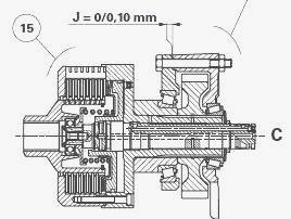
Massey Ferguson 6497, 6499 - Driving pinion
for 1000 rpm PTO
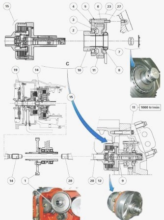
Parts list - (1) Hydraulic pump drive pinion (2)
Bearing cone (3) Bearing cup (4) Cover (5) Shim(s) (6) Unit (7) Bearing
cone (8) Bearing cup (10) Spacer (11) 1000 rpm driving pinion (12)
Circlip (14) Primary shaft (15) Clutch unit assembly (19) Mainshaft (23)
Unit/driving pinion assembly (27) Screw (28) Secondary shaft
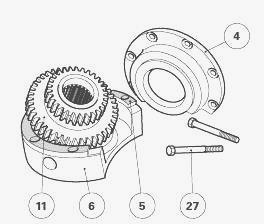
Exploded view of driving pinions
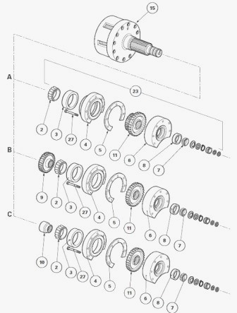
Parts list - (2) Bearing cone (3) Bearing cup (4) Cover
(5) Shim(s) (6) Unit (7) Bearing cone (8) Bearing cup (9) 540 or 750 rpm
driving pinion (version B) (10) Spacer (11) Double driving pinion (11)
1000 rpm driving pinion (15) Clutch unit assembly (23) Unit/driving
pinions assembly (27) Screw
Split the PTO housing from the centre housing to gain access to the
following main components: clutch unit (15) and unit/driving pinions
(23) assemblies; cover (4); bearing cones and cups (2)(3) and (7)(8).
Removing and refitting the driving pinions and
bearings
Remove the block consisting of the PTO clutch (15) and unit/driving
pinions (23) assemblies from the PTO housing. Split assembly (15) from
assembly (23).
MF 6497, 6499 - Driving pinions for 2 speed
PTO with interchangeable output shaft
Removal (On the unit/driving pinions assembly) - Take off: bearing cone
(7); screws (27); cover (4), the shim(s) (5).
Take out the double driving pinion (11) from unit (6). If necessary:
drive out the bearing cups (3) (8); extract the bearing cone (2) from
the clutch unit assembly (15).
Refitting (On the unit) - If disassembled, fit cups (3) (8) in cover (4)
and unit (6) respectively.
Refit: driving pinion (11); shim(s) (5), only if the bearing do not need
shimming. Otherwise, temporarily exclude this (these) shim(s); cover
(4), screws (27); bearing cone (7). If disassembled, fit bearing cone
(2) onto the clutch unit assembly (15) using a press and a suitable
fixture; If necessary, shim the bearings.
Massey Ferguson 6497, 6499 - Driving pinions
for 2 speed PTO with jaw coupler on output shaft
Removal (On the unit/driving pinions assembly) - Take off: bearing cone
(7); screws (27); driving pinion (9)/bearing cone (2); cover (4),
shim(s) (5). On the driving pinion (11) from unit (6). If necessary:
Drive out the bearing cups (3) (8); extract the bearing cone (2) from
the driving pinion (9).
Refitting (On the unit) - If disassembled, fit cups (3) (8) in cover (4)
and unit (6) respectively.
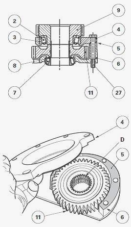
Refit the driving pinion (11) in the unit (6), with the offset "D"
turned to face the cover (4). Refit: shim(s) (5), only if the bearing do
not need shimming. Otherwise, temporarily exclude this (these) shim(s);
cover (4), screws (27); bearing cone (7). If removed, fit the bearing
cone (2) on the driving pinion (9), using a press and a suitable tool.
If necessary, shim the bearings.
MF 6497, 6499 - Driving pinion for 1000 rpm
PTO
Removal (On the unit/driving pinion assembly) - The servicing method for
the unit/driving pinion assembly (23) is similar to that applied for the
unit/driving pinions assembly (23) of 2 speed PTO with jaw coupler on
output shaft. The spacer (10) simply replaces the driving pinion (9).
Refitting (On the unit) - The servicing method for the unit (6) is
similar to that applied for the unit (6) of 2 speed PTO with jaw coupler
on output shaft. The spacer (10) simply replaces the driving pinion (9).
Reassemble the clutch unit (15) and unit/driving pinions (23)
assemblies. Refit the block consisting of the PTO clutch (15) and
unit/driving pinions (23) assemblies from the PTO housing.
Massey Ferguson 6497, 6499 - Removing and
refitting the shafts
Removal
Mainshaft (19) - Disassemble the tractor between the engine and the
gearbox. Remove the mainshaft.
Primary shaft (14) - Split the tractor between the gearbox and the
intermediate housing (Cab integral with centre housing). Remove the
primary shaft.
Secondary shaft (28) - Split the rear PTO housing from the centre
housing. Remove the secondary shaft.
Refitting
Mainshaft (19) - Refit the mainshaft. Assemble the tractor between the
engine and the gearbox.
Primary shaft (14) - Refit the primary shaft. Assemble the tractor
between the gearbox and the intermediate housing (Cab integral with
centre housing).
Secondary shaft (28) - Refit the secondary shaft. Assemble the rear PTO
housing to the centre housing.
MF 6497, 6499 - Shimming the bearings
Temporarily exclude the original shims (5). Temporarily reassemble the
clutch unit (15) and unit/driving pinions (23) assemblies.
Temporarily attach the cover (4) onto the unit (6) using the four
original screws (27) and locally made nuts (14). Immobilise the
unit/driving pinions assembly (23) in a vice with protective jaws. Place
the dial gauge feeler pin at the end of the sleeve (10). Pull very hard
on the clutch unit assembly (15), while turning it from left to right,
in order to “seat” the bearing cone (7) correctly in the cup (8).
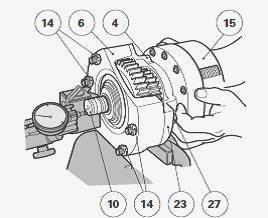
Set the dial gauge to zero. Repeat operation, pushing hard to correctly
seat the bearing cone (2) in the cup (3). Measure the clearance with the
dial gauge. Depending on the clearance measured, select a thickness of
shim(s) (5) to obtain a clearance of J = 0 to 0.10 mm. If possible, shim
so as to obtain minimum tolerance. Split the clutch unit assembly (15)
from the unit/driving pinions assembly (23). Slide the definitive
shim(s) (5) selected during operation between the unit (6) and its cover
(4). Definitively reassemble the clutch unit (15) and unit/driving
pinions (23) assemblies. Allow for refitting assemblies (15) and (23)
onto the PTO housing. Assemble the rear PTO housing to the centre
housing.
________________________________________________________________________________
________________________________________________________________________________
________________________________________________________________________________________
 SPECS
SPECS LOADERS
 MAINTENANCE
 PROBLEMS
________________________________________________________________________________________
________________________________________________________________________________________
| MF TRACTORS SPECIFICATIONS |
 130
130 133
133 145
145 155
155 158
158________________________________________________________________________________________
 165
165 175
175 185
185 188
188 230
230________________________________________________________________________________________
 254
254 254S
254S 284S
284S 294
294 353
353________________________________________________________________________________________
 290
290 362
362 375
375 390
390 398
398________________________________________________________________________________________
 399
399 590
590 690
690 1010
1010 1030
1030________________________________________________________________________________________
 1020
1020 1150
1150 2620
2620 2640
2640 2645
2645________________________________________________________________________________________
 1540
1540 1736
1736 2660
2660 3065
3065 3095
3095________________________________________________________________________________________
 3650
3650 3680
3680 4255
4255 4355
4355 4370
4370________________________________________________________________________________________
 3630
3630 3635
3635 4245
4245 4445
4445 4609
4609________________________________________________________________________________________
 4710
4710 5435
5435 5475
5475 5610
5610 5711
5711________________________________________________________________________________________
 6150
6150 6170
6170 6180
6180 6270
6270 6290
6290________________________________________________________________________________________
 6445
6445 6499
6499 6614
6614 6713
6713 7465
7465________________________________________________________________________________________
 7495
7495 7614
7614 7622
7622 7715
7715 7726
7726________________________________________________________________________________________
 8210
8210 8270
8270 8650
8650 8727
8727 GC1705
________________________________________________________________________________________
| MF FRONT END LOADERS |
 1464 Loader
 1466 Loader
 1040 Loader
 1070 Loader
 905 Loader
________________________________________________________________________________________
 906 Loader
 915 Loader
 916 Loader
 921 Loader
 926 Loader
________________________________________________________________________________________
 931 Loader
 933 Loader
 936 Loader
 938 Loader
 939 Loader
________________________________________________________________________________________
 940 Loader
 941 Loader
 945 Loader
 946 Loader
 948 Loader
________________________________________________________________________________________
 949 Loader
 950 Loader
 951 Loader
 955 Loader
 956 Loader
________________________________________________________________________________________
 958 Loader
 960 Loader
 961 Loader
 965 Loader
 966 Loader
________________________________________________________________________________________
 968 Loader
 975 Loader
 976 Loader
 978 Loader
 985 Loader
________________________________________________________________________________________
 FL.3114 X
 FL.3419 X
 FL.3522
 FL.3615
 FL.3619
________________________________________________________________________________________
 FL.3817
 FL.3819
 FL.3823
 FL.4018
 FL.4121
 916X Loader
 921X Loader
 926X Loader
 931X Loader
 936X Loader
________________________________________________________________________________________
 941X Loader
 946X Loader
 951X Loader
 956X Loader
 988 Loader
________________________________________________________________________________________
 FL.4125
 FL.4227
 FL.4124
 FL.4220
 FL.4323
________________________________________________________________________________________
 FL.4327
 FL.4621
 FL.4624
 FL.4628
 FL.5033
________________________________________________________________________________________
 DL95 Loader
 DL100 Loader
 DL120 Loader
 DL125 Loader
 DL130 Loader
________________________________________________________________________________________
 DL135 Loader
 DL250 Loader
 DL260 Loader
 L90 Loader
 L100 Loader
________________________________________________________________________________________
 L105E Loader
 L210 Loader
 1014 Loader
 1016 Loader
 1462 Loader
________________________________________________________________________________________
 1525 Loader
 1530 Loader
 232 Loader
 838 Loader
 848 Loader
________________________________________________________________________________________
 246 Loader
 1036 Loader
 1038 Loader
 1080 Loader
 856 Loader
________________________________________________________________________________________
| MF TRACTORS MAINTENANCE |
 1010
1010 1020
1020 1030
1030 1035
1035 1040
1040________________________________________________________________________________________
 1045
1045 1080
1080 1085
1085 1120
1120 1125
1125________________________________________________________________________________________
 1140
1140 1160
1160 1165
1165 1180
1180 1190
1190________________________________________________________________________________________
 1205
1205 1210
1210 1215
1215 1220
1220 1225
1225________________________________________________________________________________________
 1230
1230 1233
1233 1235
1235 1240
1240 1260
1260________________________________________________________________________________________
| MF TRACTORS TROUBLESHOOTING | ||||
| 1652 | 1749 | 2620 | 2725 | 2805 |
| 3050 | 3120 | 3640 | 3709 | 4245 |
| 4455 | 5320 | 5455 | 5613 | 6150 |
| 6280 | 6480 | 6615 | 7618 | 7720 |